Printed circuit board replacement, Chapter 3 repair procedures – Rice Lake Scout Pro Series Portable, Ohaus - Service Manual User Manual
Page 16
3-2
CHAPTER 3 REPAIR PROCEDURES
3.1.1 Cover Removal (Cont.)
5. Remove the 4 AA batteries from inside the battery compartment and replace the Battery
Compartment Cover (12).
6. Slide the Lockswitch to to the unlocked position to gain access to one of the cover screws.
Remove the 3 Cover Screws as shown in Figure 3-2.
7. Turn the balance over in an upright position and carefully lift the Top Cover (6) from the
balance Base (10).
8. After repairs and or adjustments have been made, reassemble the balance in the reverse
order.
3.1.2 Printed Circuit Board (9) Replacement
In an effort to keep service costs down, it is suggested that if the Printed Circuit Board (9) is suspected
of being faulty, it should be replaced rather than repaired.
To replace the Printed Circuit Board (9) , proceed as follows:
1. Remove the balance cover, refer to paragraph 3.1.1.
CAUTION
WHEN HANDLING THE PRINTED CIRCUIT BOARD,
HANDLE BY EDGES ONLY! DO NOT TOUCH FOIL SIDE
OF BOARD. STATIC DISCHARGE MAY DAMAGE SOME
COMPONENTS.
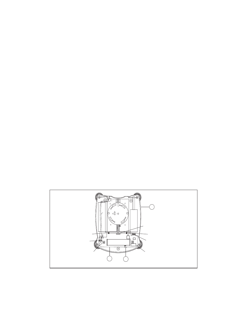
2. The Printed Circuit Board (9) is fastened in place by 2 clips which are part of the Base (10)
and 2 screws located on top of the Printed Circuit Board. In addition, a Calibration Lock
(15)(small plastic piece) is positioned at the front of the Printed Circuit Board. See Figure
3-3.
Figure 3-3. Printed Circuit Board Removal.
U9
CAL
J6
J11
LCD DISPLAY
U8
U7
J2
C4
BLK
RED
9
15
CLIP
CLIP
MOUNTING
SCREW
MOUNTING
SCREW
J6 CONNECTOR
10
PCB
CAL LOCK
BASE
J11 RS232 CONNECTOR
J2 BATTERY
CONNECTOR