Figure 4-1. load cell mounting, Keep track of the washer above the load cell, 3 corner corrections – Rice Lake Floor Scales - SURVIVOR FB Series Electronic Flexure Base User Manual
Page 10
6
FB Series
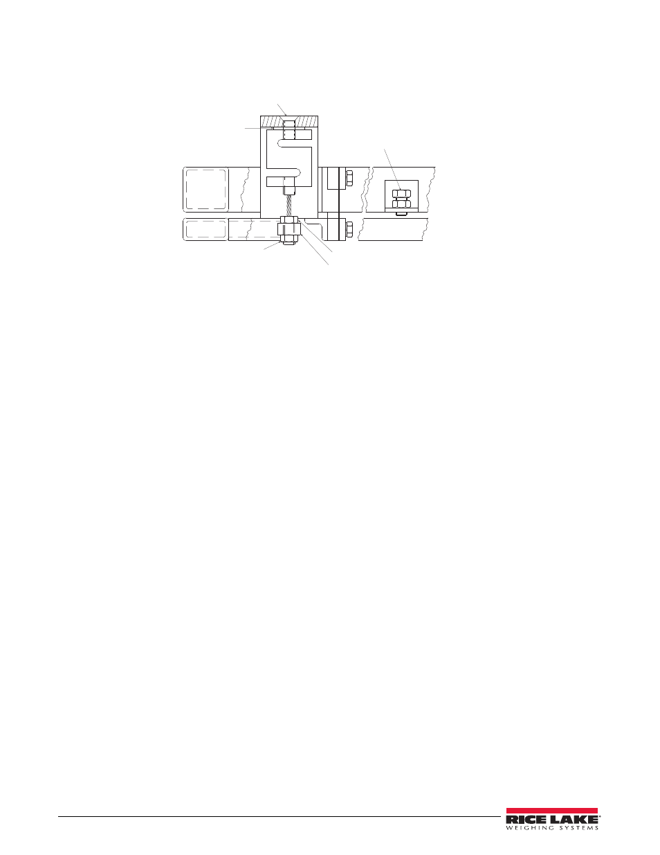
Figure 4-1. Load Cell Mounting
3. Remove the signal cable access hole cover plate. Pull the cable from the plate and pass it through the base.
4. Remove the lower lock nut from the wire rope and back off the upper lock nut.
5. Using a hex allen wrench in the flathead bolt, and an adjustable wrench to hold the load cell body, remove
the load cell.
6. Keep track of the washer above the load cell.
7. Remove the wire rope from the defective load cell and screw it into the new load cell to the approximate
position it was in the old load cell.
8. Insert the wire rope into the nose iron hole and turn the lower nut on loosely.
9. Hold the flat washer in place, and screw the flathead bolt into the top of the load cell. Tighten the flathead
bolt securely using the hex allen wrench and adjustable wrench.
10. Tighten the lower lock nut on the wire rope against the nose iron finger tight only. Lock the upper nut down
against the nose iron.
11. Release the load cell shock-stop bolts and set the clearance to 1/16''.
12. Lock into place with the lock nuts so the bolts do not loosen and contact the frame during weighing.
13. Pass the signal cable through the access hole and follow Steps 6-11 on page 2.
14. Replace the deck assembly and recalibrate according to Section 3.
4.3
Corner Corrections
For the current tolerances that apply for shift tests, see NIST Handbook 44 Field Manual, sec. 2.2, par. TN 4.4.
Conduct a shift test on each corner with 25% of the scale capacity. Each FB floor scale is factory sealed to NIST
specs. However, if major repairs have been performed on the unit, corner corrections may be required. Following is
an explanation of that process.
1. Locate various shims at the top of each pivot head and behind the load flexures.
2. Add shims to increase a corner’s reading, subtract shims to decrease a corner’s reading. See Figure 4-2.
Flathead Bolt
Flat Washer
Lower Lock Nut
Upper Lock Nut
Nose Iron
Loadcell Shock-Stops:
Locked down for shipping.
Set 1/16" clearance for weighing.