Figure 4. signal main board – Rice Lake EL204 Signal Trim User Manual
Page 3
3
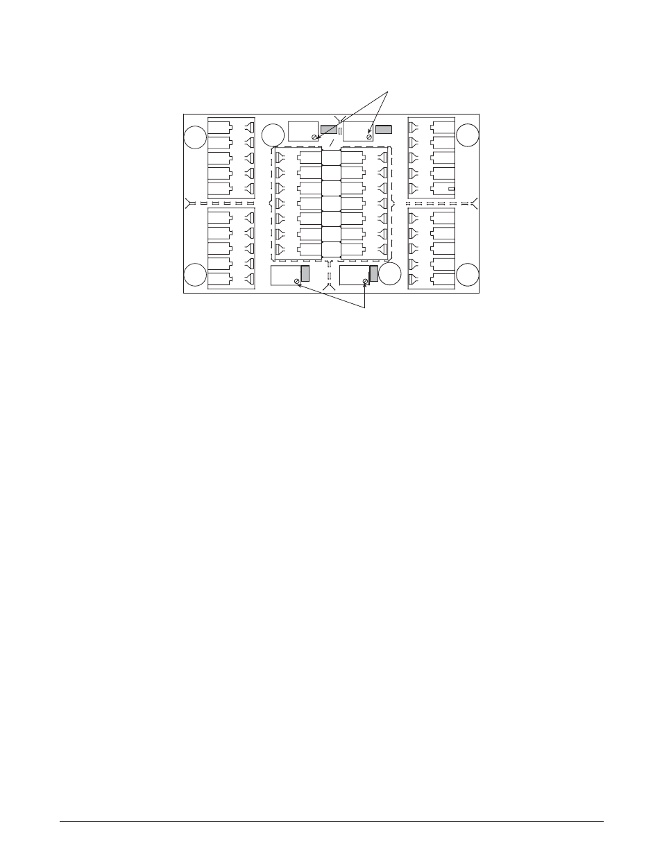
Figure 4. Signal Main Board
4. Zero the indicator and place calibrated test weights over each load cell in turn. The amount of test weights
to be used will depend on the scale configuration; for specific recommendations, refer to Handbook 44
Field Manual, published by the Institute for Weights and Measures. For a four-cell platform, it’s
recommended using 25% of scale capacity.
5. Record the value displayed on the indicator after the test weight is placed in turn on each corner (directly
over the load cell), without allowing the weight to overhang the sides. Allow the scale to return to zero
each time to check for friction or other mechanical problems. Select the load cell which has the lowest
value as your reference point. This cell will not be trimmed.
6. Replace the same test load over each cell in turn. Using the corresponding potentiometer, trim each cell
down to equal the reference load cell. As corner corrections are somewhat interactive, check all cells again
for repeatability. If necessary, repeat steps four and five.
7. Pull excess cable out of the enclosure and tighten the cord grip assemblies with a wrench. To be watertight,
each cord grip must be tightened so the rubber sleeve begins to protrude from the hub.
8. Unused hubs must be properly plugged to prevent moisture entry. See the Electronic Replacement Parts
and Components catalog to order extra hole plugs.
9. Remove the desiccant from the plastic bag and insert the desiccant bag into the junction box before
closing. Inspect the desiccant during normal service and change the desiccant as needed.
10. Replace the cover and tighten the cover screws in an alternating pattern to 15 in/lb to be certain the
junction box cover is compressed equally in all locations.
JP4
JP2
PT4
PT3
JP3
PT1
EXP
PT2
JP1
1
CELL4
1
CELL1
1
CELL3
1
CELL2
IND
-EX
-SI
SHD
+SI
+EX
M
R
N
I
-SI
S2C
I
A
G
+EX
+SI
-SI
SHD
-EX
I
S
G
A
L
T
+SI
M
S
I
N
L
T
R
+EX
-EX
-SI
SHD
+SI
+EX
+SI
-EX
-SI
SHD
-EX
SHD
+SE
-SE
+EX
Potentiometers
Jumper Locations
JP1 and JP 2
Shaded
Jumper Locations
JP3 and JP 4
Shaded
Potentiometers