3 mounting and wiring the mast and indicator, 4 corner trimming – Rice Lake DeckHand/DeckHand Rough-n-Ready System User Manual
Page 8
4
2.3
Mounting and Wiring the Mast and Indicator
Assembling Mast to Base
Remove back plate from mast. Carefully insert mast into window in base. Align holes and secure with fasteners
(refer to Figure 4-1). Wrap excess cable around hooks in mast. Re-assemble back plate to mast.
Attaching Indicator Bracket to Mast
The DeckHand is supplied with a swivel bracket for a variety of RLWS indicators. If using a different bracket, bolt
it onto the mounting plate on the mast with the bolts, washers, and nuts provided.
Set the two large plastic washers provided near the thumbscrew bolts used to hold the indicator in the bracket. Put
the bolts and washers within close reach of the bracket—they are needed for the next step.
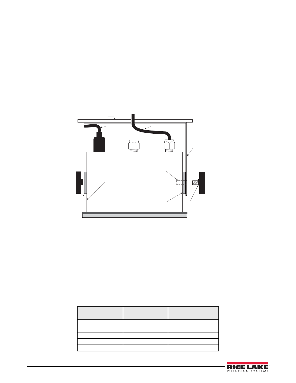
Mounting the Indicator
Spread the bracket arms enough to slide the indicator between the bracket arms. Line up the bracket holes with the
threaded enclosure holes. Slide a plastic pivot washer between each arm and the indicator enclosure at the holes.
Figure 2-2. Top View of Indicator and Bracket
Insert the thumbscrew bolts through the bracket arms, through the washers, and into the threaded holes of the
indicator enclosure. Tighten bolts snugly so the indicator remains at the desired viewing angle.
Wiring Load Cell Cable to Indicator
The load cell cable from the J-box is pre-wired to the indicator terminal inside the j-box. Attach the loose end of
this cable to the indicator’s load cell input terminal according to the corresponding pin functions on the j-box
indicator terminal. When completed, tighten the cord grip around the cable where it passes through the indicator
case.
2.4
Corner Trimming
The DeckHand scales are factory-trimmed so each load cell shares an equal part of the weight load.
Further corner-trimming is unnecessary unless a load cell is replaced. See Section 3.0 for complete information on
corner-trimming after load cell replacement.
Load Cell Cable
Color Code
J-Box Terminal
Load Cell Cable Color
(load cells to j-box)
Green
+ Excitation
Green/Blue
Black
– Excitation
Black/Brown
Red
+ Signal
Red
White
– Signal
White
Bare
Shield
Yellow
Table 2-1. Load Cell Cable Wiring Code
Plastic Pivot Washer
Swivel Bracket
Threaded Insert
Thumbscrew Bolt
Load Cell Cable
AC Power
Indicator Enclosure
Mounting Plate