Rice Lake WeighVault for CW-90/CW-90X - Installation Instructions User Manual
Weighvault, Installation instructions, Cw-90/90x
April 2011
119661
CW-90/90X
WeighVault
™
Installation Instructions
Option PN 117358
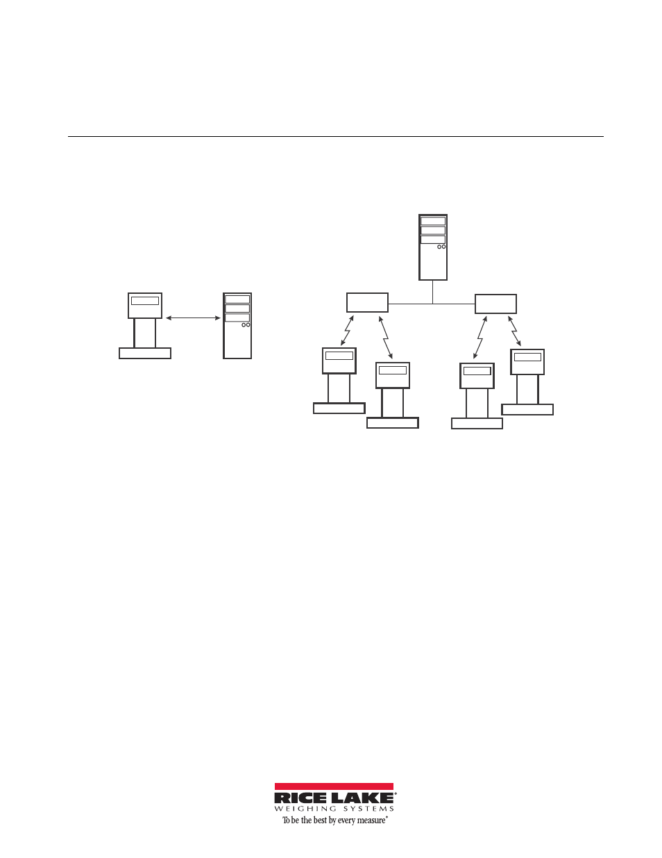
WeighVault allows users to add, edit, and access IDs over a Ethernet or WLAN network connection. WeighVault
surpasses the indicator's onboard ID limitation and eliminates front-panel entry of ID parameters. It also collects
data as transactions occur, and provides detailed transaction and productivity reports which can be exported to
Excel, Word, or PDF.
Scale
Scale
Scale
Scale
Scale
WLAN or
Ethernet
PC
Network
Server
AdHoc connection with
a single scale and PC
Router or
Access Point
Router or
Access Point
Infrastructure connection with multiple scales
Company Network
Figure 1. WeighVault possible connections
Requirements
For WeighVault to function, you must meet the
following criteria:
•
Indicator must be connected to a PC via a
wired Ethernet or wireless network.
•
The PC running the WeighVault Service must
have a static IP address.
•
Known IP address and subnet of the host PC;
if connecting via WLAN, known network
SSID and security settings (pass keys and
phrases).
•
Specific WeighVault settings must be
configured in the indicator’s menu.
Ethernet/WLAN Connection
The physical connection between the indicator and a
network can be accomplished using:
•
Internal Ethernet TCP/IP Interface Option,
PN 72117
•
Internal WLAN Interface Option, PN 108671
•
External RS-232 to Ethernet/WLAN
converter
Installing the Internal Ethernet or WLAN Options
NOTE: For detailed instructions, refer to the manuals supplied
with the option kits. Perform the installation at an ESD-safe
workstation.
1. Disconnect the indicator from its power
source.
2. Remove the back cover from the indicator.
3. Remove the plug (if installed) from the larger
cord grip to allow installation of the Ethernet
WLAN antenna.
4. Remove the Ethernet or WLAN option card
from its ESD bag.
5. If installing WLAN, carefully screw the
included antenna onto the end of the white RF
cable. In addition, set the WiPt/Xcvr switch to
the Xcvr position, and place both CFG/LOOP
jumpers in the CFG position.
6. Install the 2 plastic standoffs into the two
holes on the indicator's CPU board located
approximately 1.5 inches to the left of J5.
Document Outline
- Requirements
- Ethernet/WLAN Connection
- Installing the Internal Ethernet or WLAN Options
- WeighVault service and editor installation
- Configuring the CW-90/90X
- PC or Server configuration
- Configuration Internal Ethernet or WLAN Option Cards
- Installing Device Installer on your PC
- Initial Configuration of WLAN Option Card via RS-232
- Ethernet and WLAN Option Card Configuration using Device Installer
- Configuring an External RS-232 to Ethernet or WLAN converter
- Using WeighVault