7 enclosure reassembly, 8 cpu board removal, 9 fuse replacement – Rice Lake Lift Truck/Pallet Jack Scales - CLS-Series User Manual
Page 36: Enclosure reassembly, Cpu board removal, Fuse replacement, Aution
32
CLS Series Service Manual
Expansion Board Serial Port Assignments
Serial port numbers are reserved for each option card
slot, regardless of the type of cards actually installed.
Two port numbers are reserved for each slot that could
contain a dual-channel serial expansion card.
Table 5-8 shows the port numbers assigned to each
slot.
5.2.7
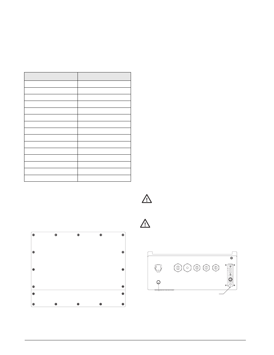
Enclosure Reassembly
Once cabling is complete, position the backplate over
the enclosure and reinstall the backplate screws. Use
the torque pattern shown in Figure 2-12 to prevent
distorting the backplate gasket. Torque screws to 15
in-lb (1.7 N-m).
Figure 5-12.
5.2.8
CPU Board Removal
If you must remove the
920i
CPU board, use the
following procedure:
1. Disconnect power to the indicator. Remove
backplate as described in Section 2.2 on
page 6.
2. Unplug connectors J9, J10, and J11 (serial
communications), J2 (digital I/O), P1 (power
supply), and connectors to any installed
option cards.
3. Remove any installed option cards.
4. Remove the five phillips head screws and two
kep nuts from the CPU board.
5. Gently lift up the CPU board, then disconnect
connectors J12 (power to display), J4 (ribbon
cable, J3 (keypad connector), then the cable
J8 (Port 2 serial port).
6. Remove CPU board from the enclosure. If
necessary, cut cable ties to shift cables out of
the way.
To replace the CPU board, reverse the above
procedure. Be sure to reinstall cable ties to secure all
cables inside the indicator enclosure.
5.2.9
Fuse Replacement
Fuses for the universal and deep enclosure models of
the
920i
are located under a cover plate on the outside
of the enclosure. Remove the cover plate, replace the
fuses, and reinstall the cover plate (see Figure 5-13).
To protect against the risk of fire, replace
fuses only with same type and rating fuse.
See Section 10.14 on page 126 for
complete fuse specifications.
Interface board and fuse access cover
plates must be in place for use in NEMA
4X/IP66 applications.
l
Figure 5-13. Interface Board and Fuse Locations,
Universal Model
Slot Number
Serial Port Assignments
CPU board
1–4
1
5–6
2
7–8
3
9–10
4
11–12
5
13–14
6
15–16
7
17–18
8
19–20
9
21–22
10
23–24
11
25–26
12
27–28
13
29–30
14
31–32
Table 5-8. Expansion Board Serial Port Assignments
5PSRVFCBDLQMBUFTDSFXT
UPJOMC /N
#AUTION
#AUTION
5PSRVFGVTFBOEJOUFSGBDFCPBSEBDDFTTDPWFSTUP
JOMC /N
*OUFSGBDF#PBSE
1PXFS4XJUDI