0 board replacement, 1 cls-420 cpu board replacement, 1 cable grounding – Rice Lake Lift Truck/Pallet Jack Scales - CLS-Series User Manual
Page 25: Board replacement, Cable grounding, Warning
Board Replacement
21
5.0
Board Replacement
Use the following procedures in the event that the CPU board on either the 420 or the 920i need to be replaced.
Board replacement for the 420 indicator is covered in Section 5.1 and board replacement for the 920i indicator is
covered in Section 5.2.
5.1
CLS-420 CPU Board Replacement
The indicator enclosure must be opened to connect cables for load cells, communications, digital inputs, and
analog output.
The 420
has an on/off switch for the load cells and processor functions. Before opening the unit, ensure the
power cord is disconnected from the forklift battery power source.
5.1.1
Cable Grounding
Except for the power cord, all cables routed through
the cord grips should be grounded against the
indicator enclosure. Do the following to ground
shielded cables:
•
Use the lockwashers, clamps, and kep nuts
provided in the parts kit to install grounding
clamps on the enclosure studs adjacent to cord
grips. Install grounding clamps only for cord
grips that will be used; do not tighten nuts.
•
Route cables through cord grips and
grounding clamps to determine cable lengths
required to reach cable connectors. Mark
cables to remove insulation and shield as
described below:
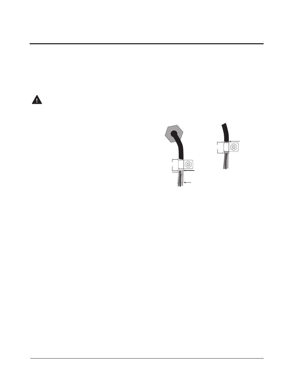
•
For cables with foil shielding, strip insulation
and foil from the cable half an inch (15 mm)
past the grounding clamp (see Figure 5-1).
Fold the foil shield back on the cable where
the cable passes through the clamp. Ensure
silver (conductive) side of foil is turned
outward for contact with the grounding
clamp.
•
For cables with braided shielding, strip cable
insulation and braided shield from a point just
past the grounding clamp. Strip another half
inch (15 mm) of insulation only to expose the
braid where the cable passes through the
clamp (see Figure 5-1).
•
For load cell cables, cut the shield wire just
past th e gro unding clamp . Shield wire
function is provided by contact between the
cable shield and the grounding clamp.
•
Route stripped cables through cord grips and
clamps. Ensure shields contact grounding
clamps as shown in Figure 5-1. Tighten
grounding clamp nuts.
•
Finish installation using cable mounts and ties
to secure cables inside of indicator enclosure.
Figure 5-1. Grounding Clamp Attachment for
Foil-Shielded and Braided Cabling
Warning
$PSEHSJQ
*OTVMBUFEDBCMF
'PJM TJMWFSTJEFPVU
(SPVOEJOHDMBNQ
4IJFMEXJSF DVU
-FOHUIPGGPJMCFGPSFGPMEJOH
CBDLPODBCMFJOTVMBUJPO
$VUJOTVMBUJPOIFSF
GPSGPJMTIJFMEFEDBCMFT
#SBJE
$VUJOTVMBUJPOIFSF
GPSCSBJEFEDBCMFT
/05&*OTUBMMMPDLXBTIFST
mSTU BHBJOTUFODMPTVSF
VOEFSHSPVOEJOHDMBNQ