Analog output calibration – Rice Lake 880 Performance Series Panel Mount Indicator/Controller - Analog Output Card Option Installation Manual User Manual
Page 4
J1
J2
J3
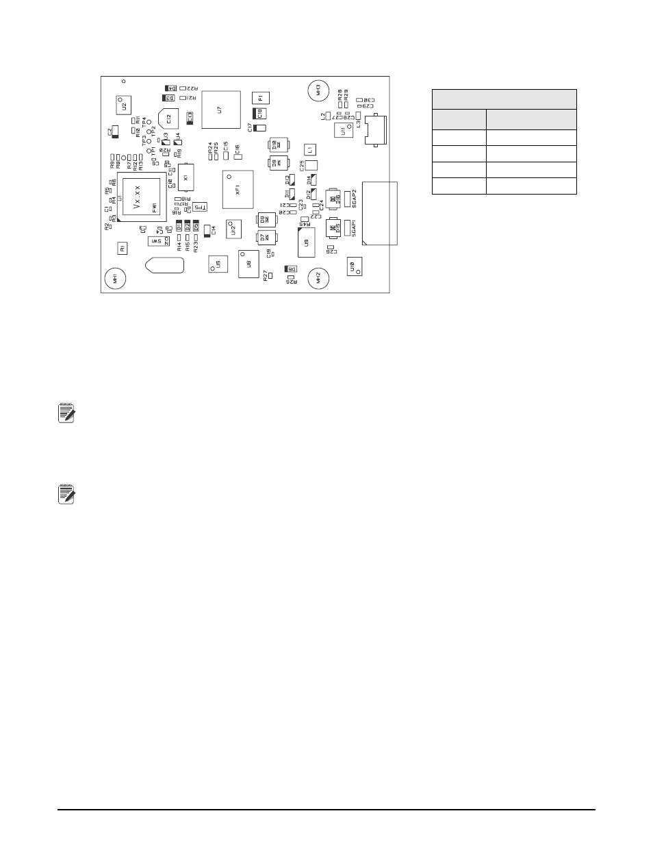
Connector J1
Pin
Signal
1
– Current Out
2
+ Current Out
3
– Voltage Out
4
+ Voltage Out
Table 1. Analog Output Card
Pin Assignments
4
Analog Output Card Installation
Figure 2. Analog Output Card Installation
15. Connect to the analog output card as shown in Table 1. Voltage or current output is configured via
software.
16. Reassembly control box to the DIN rail.
17. Reconnect all connectors to the back of the controller assembly.
18. Reconnect power to the indicator.
Note
The indicator automatically recognizes all installed option cards when the unit is powered on. No
hardware-specific configuration is required to identify the newly-installed card to the system.
Analog Output Calibration
The following calibration procedure requires a multimeter to measure voltage or current output from the analog
output module.
Note
The analog output must be calibrated after the indicator itself has been configured and calibrated.
1. Enter setup mode and go to the ALGOUT menu (see Figure 3):
• Set MODE to track either gross or net weight from that scale
• Set OUTPUT for 0–10 V, 0–20 mA or 4–20 mA output
• Set ERRACT to specify how the analog output will respond to system error conditions
• Set MIN to lowest weight value to be tracked by the analog output
• MIN NEG – set to on to specify the minimum weight (MIN parameter) is a negative value.
• Set MAX to highest weight value to be tracked by the analog output
• MAX NEG – set to on to specify the maximum weight (MAX parameter) is a negative value.
• Tweak zero – adjust the analog output zero calibration.
• Tweak span – adjust the analog output span calibration.