Rice Lake 920i USB Programmable Indicator Controller - 6V DC-to-DC Power Supply User Manual
Page 3
AddendumTitle
3
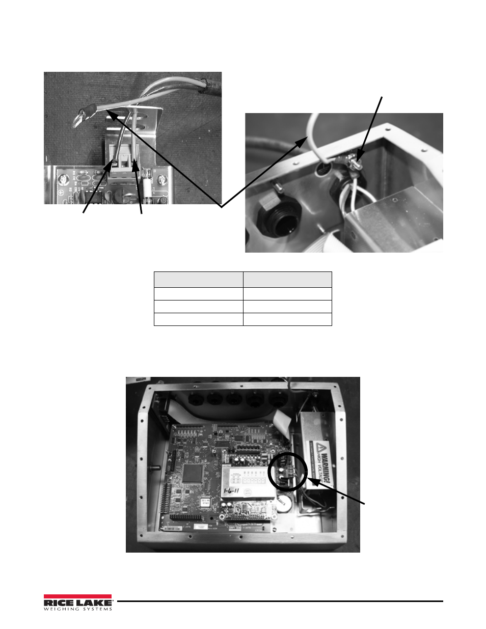
6. Connect the ground wire that comes from the cable to the ground lug on the indicator. Attach the red and
black wires coming from the cable to the power supply board. Proper wire connections are shown in Table 1.
Blue
Ground
Wire
Ground lug
Black Wire
Red Wire
Figure 5. Install + and - Voltage Wire and Connect Ground Wire
Table 1. Wiring to Power Supply
Wire Color
Signal
Blue
Ground
Red
+V
Black
-V
7. Carefully align the power supply to existing location and use screws provided to secure the power supply
to the enclosure.
Plug in location on
the 920i CPU board
.
Figure 6. Plug in the DC Output Side of Power Supply to 920i CPU Board
8. Carefully plug in the +/- 6 VDC output side of the power supply to the CPU board. It’s location is noted in
This manual is related to the following products:
- 920i Programmable HMI Indicator/Controller - 6V DC-to-DC Power Supply 920i FlexWeigh Systems - 6V DC-to-DC Power Supply Installation Instructions 820i Programmable Indicator/Controller - 6V DC-to-DC Power Supply Installation Instructions 720i Programmable Indicator/Controller - 6V DC-to-DC Power Supply Installation Instructions