2 devicenet network connections, 3 dip switch configuration, Section 2.3 on – Rice Lake 920i Programmable HMI Indicator/Controller - DeviceNet Interface User Manual
Page 8
4
520/720i/820i/920i
DeviceNet Installation and Programming Manual
2.2
DeviceNet Network Connections
Feed DeviceNet network cable through cord grip.
Allow enough cable for routing along inside of
enclosure to connector on the DeviceNet module.
C o n n e c t n e t w o r k c a b l e s t o c o n n e c t o r o n t h e
DeviceNet module (see Figure 2-4), then use cable
ties to secure network cables to the cable tie mounts.
Table 2-1shows the wiring color codes used for
DeviceNet connections.
Verify the color-coding or wiring
scheme for your network equipment before wiring to the
DeviceNet Interface.
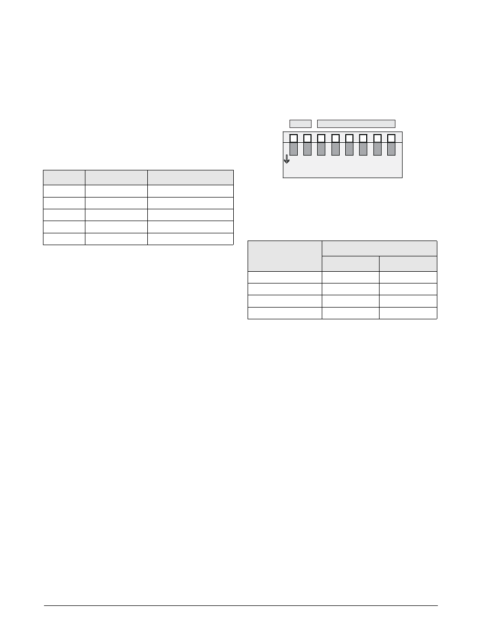
2.3
DIP Switch Configuration
A DIP switch is used to configure the DeviceNet
network baud rate and node address. Figure 2-7 shows
the DIP switch assignments.
Figure 2-7. DIP Switch Assignments
Baud Rate
Switches 1 and 2 set the baud rate of the DeviceNet
network. Use Table 2-2 to select the correct switch
settings for the network.
Node Address (MAC ID)
Switches 3–8 set the node address (MAC ID) of the
DeviceNet interface. Use Table 2-3 on page 5 to select
the switch setting for the node address.
NOTE: Setting a switch ON acts as a logical “1” and that
SW1-3 represents the most significant bit (MSB) of the node
address.
Signal
Description
Color Code
V+
Positive supply
Red
CAN_H
CAN_H bus line
White
SHIELD
Cable shield
Bare
CAN_L
CAN_L bus line
Light blue
V–
Negative supply
Black
Table 2-1. DeviceNet Color Codes
DeviceNet
Data Rate
Switch Settings
1
2
125 Kbps
OFF
OFF
250 Kbps
OFF
ON
500 Kbps
ON
OFF
Reserved
ON
ON
Table 2-2. Network Data Rate
Baud
Rate
Node Address
MSB
LSB
ON
1
2
8
5
3
4
6
7