2 installing devicenet option in the 520, Installing devicenet option in the 520, Devicenet module – Rice Lake 920i Programmable HMI Indicator/Controller - DeviceNet Interface User Manual
Page 7: W arning
Installation
3
9. Ensure no excess cable is left inside the
enclosure and tighten cord grips.
10. Reconnect power to the indicator. The
i n d i c a t o r a u t o m a t i c a l l y r e c o g n i z e s a l l
installed option cards when the unit is
p o w e r e d o n . N o h a r d w a r e - s p e c i f i c
configuration is required to identify the
newly-installed DeviceNet Interface to the
system.
Figure 2-4. Bus Adapter Card and DeviceNet Module
2.1.2
Installing DeviceNet Option in the 520
Use the following procedure to install the DeviceNet
Interface in the
520
indicator:
1. Disconnect indicator from power source.
Disconnect power before removing
indicator enclosure cover.
The
520
has no on/off switch. Before
opening the unit, ensure the power cord is
disconnected from the power outlet.
2. Place indicator on an antistatic work mat.
Remove screws that hold the enclosure cover
to the enclosure body.
Use a wrist strap to ground yourself and
protect components from electrostatic
discharge (ESD) when working inside the
indicator enclosure.
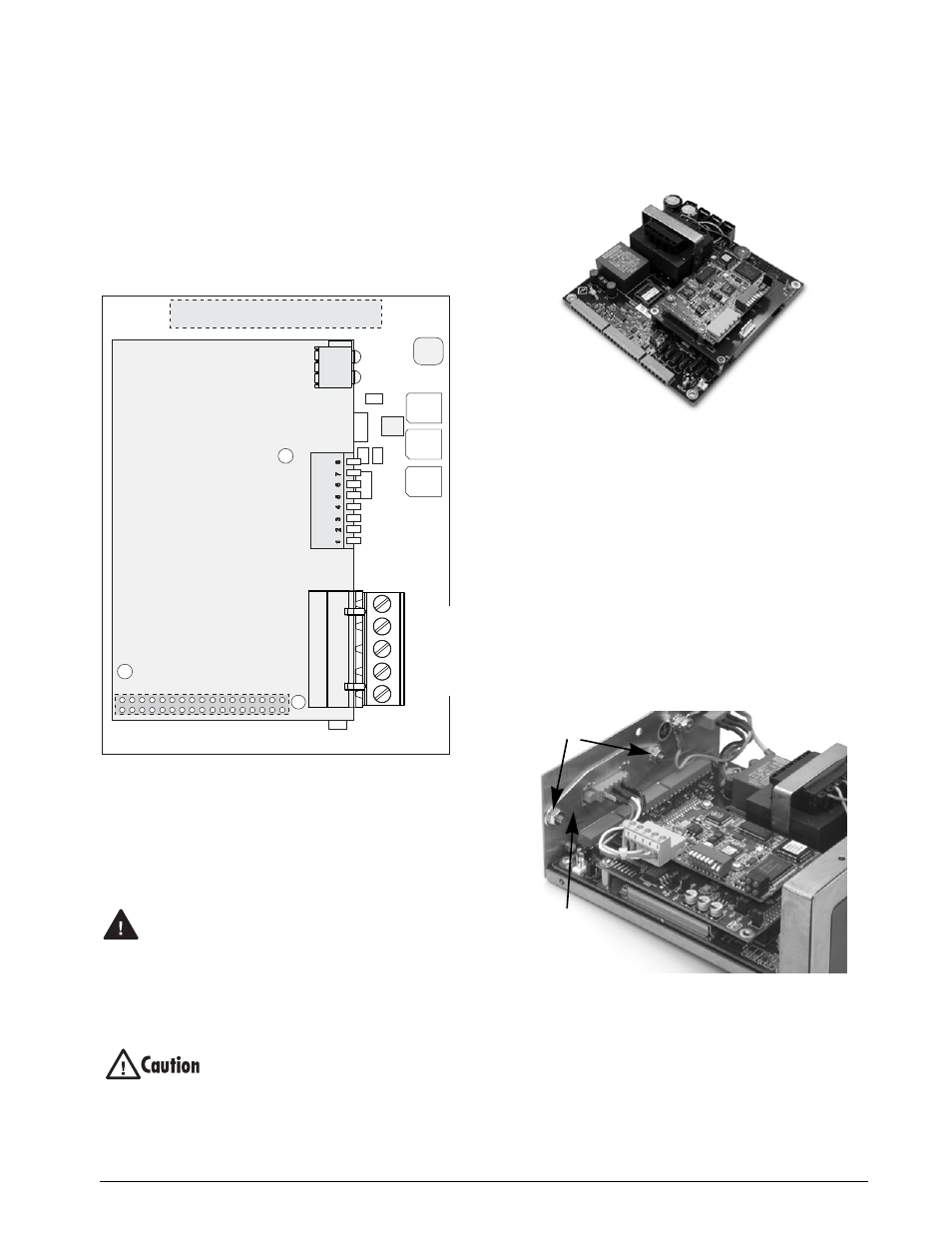
3. Carefully align the large option card
connector with connector J2 on the CPU
board (see Figure 2-5). Press
down
to seat the
option card in the CPU board connector.
Figure 2-5. Option Installed on
520 CPU Board
4. Use screws provided in the option kit to
secure the other end of the option card to the
threaded standoffs on the CPU board.
5. Install terminal block end of cable assembly
to DeviceNet option card.
6. Remove existing cover plate.
7. Re-use kep nuts to secure DeviceNet cover
plate to sta ndo ffs loca te d o n in side of
enclosure backplate (see Figure 2-6).
8. Once cabling is complete, position the cover
over the enclosure and reinstall the screws.
9. Reconnect power to the indicator.
Figure 2-6. DeviceNet Cable Assembly
10. The indicator automatically recognizes all
installed option cards when the unit is
p o w e r e d o n . N o h a r d w a r e - s p e c i f i c
configuration is required to identify the
newly-installed DeviceNet interface to the
system.
J2
TEST
3.3V
GND
J1
V+
V–
CAN_L
CAN_H
SHIELD
DeviceNet
Module
LED Array
DIP Switch
W arning
Cover Plate
Standoffs