Multifunctional monitor & logger powerlog 6s – ProgressiveRC 6S PowerLog User Manual
Page 9
-9-
Multifunctional Monitor & Logger PowerLog 6S
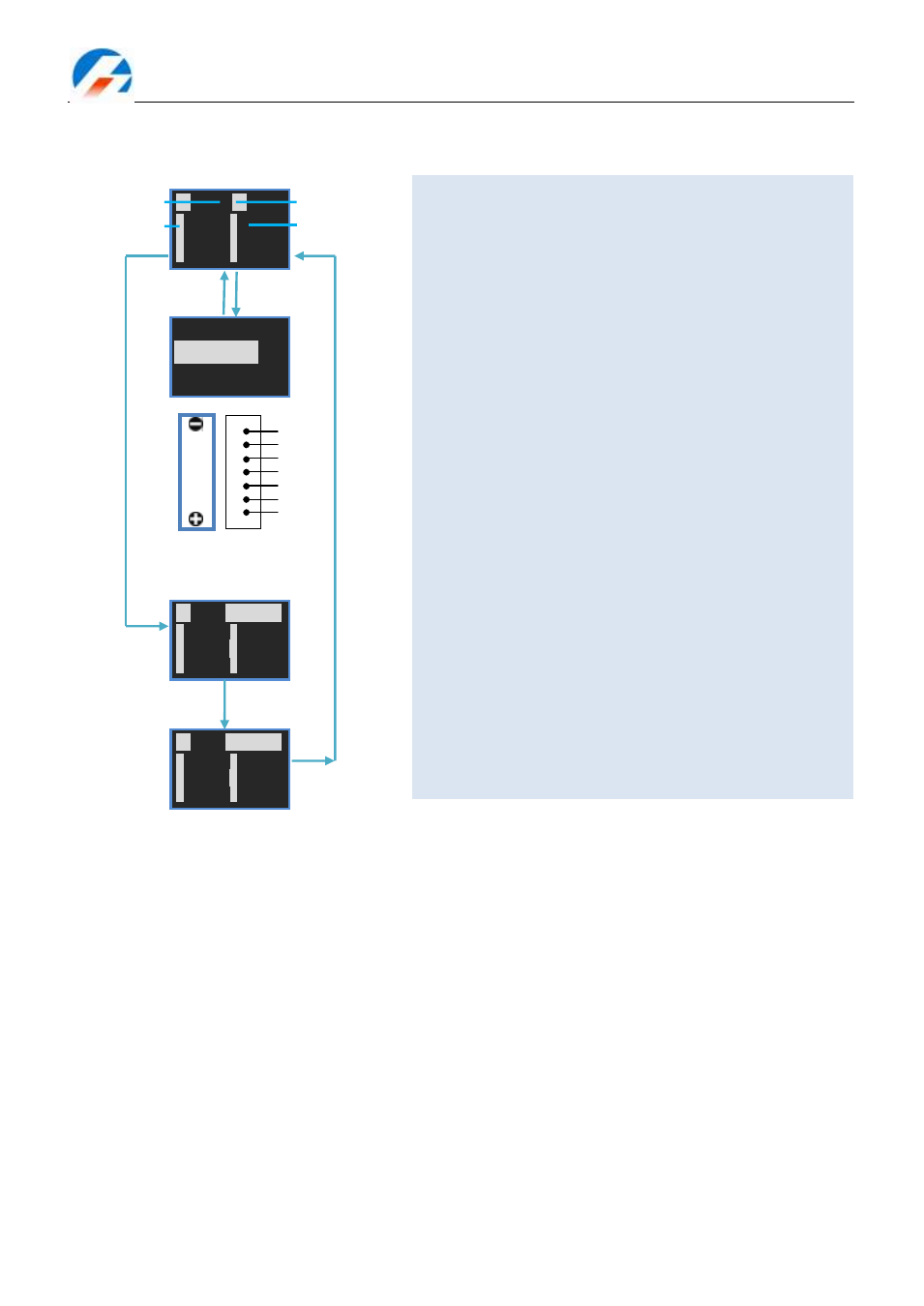
2) Cells Monitor
Monitor the input voltage of Multiple Voltage Input Port(J3)
Voltage Sum: the sum voltage of Cell Voltage 1-6
▣
V = Max. Cell Voltage – Min. Cell Voltage
‗‘ is in front of the cell with Max. Cell Voltage, while ‘‘ is
in front of the cell with Min. Cell Voltage.
Setting range
V1-V6: 0.05—28.00V
【
Difference】Displayed voltage CellVn=Vn–Vn-1 (1≤n≤
6), under the condition V6>V5>V4>V3>V2>V1>0.
【
Auto Difference】
First sorting by ascending numeric sequence between
V1-V6, then has Va1-Va6, CellVn=Van–Van-1 (1≤n≤6).
【
Each Voltage】Displayed voltage CellVn=Vn (1≤n≤6).
Press<▲>or<▼>, can shift among the interfaces of current
value, Min. peak value and Max. peak value
Reset peak value
Press<▲>+<▼>, the Min. and Max. peak value will be
replaced to be the current value.
PIN 7
PIN 1
1
2
3
4
5
6
GND
V1
V2
V3
V4
V5
V6
5S
20.63V
▣
V
75mV
1
4.110V
2
4.152V
3
4.087V
4
4.162V
5
4.120V
6
------
Max. Voltage
Difference
Cell Voltage
Voltage Sum
Cell Number
CELLS MODE
⊙Difference
○Auto Differenc
○Each Voltage
<▢>+<▼>
>3 Seconds
>3 Seconds
5S
20.63
PEAK Min
1
4.100V
2
4.150V
3
4.080V
4
4.160V
5
4.110V
6
------
5S
20.63
PEAK Max
1
4.120V
2
4.172V
3
4.097V
4
4.192V
5
4.130V
6
------
<▢> or<▼>
<▢> or<▼>
<▢> or<▼>