ProgressiveRC 6S PowerLog User Manual
Page 11
-11-
Multifunctional Monitor & Logger PowerLog 6S
4) PWM Monitor
Monitor the input pulse signal from J1
The measurement resolution of PWM is 1us,
Freq. = 1/Period.
The smaller the Period, the bigger measurement deviation
of Freq.
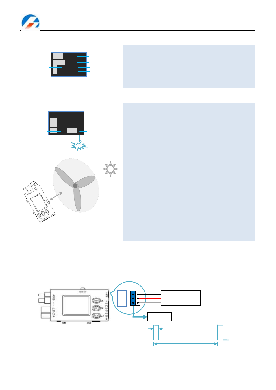
5) Tachometer Monitor
Press <▲> + <▼> for 3 seconds, the number of propeller
blades begins blinking, and then press <▲> / <▼> to
adjust the value. Press < > to confirm and return.
Reset Max. RPM
Press <▼>+ for 3 seconds, the peak value will be
replaced to be the current value.
Setting range
RPM: 0– 99999
Blade: 1– 20
Right measuring methods:
Tachometer sensor faces directly to the rotary surface and
the light source, making the distance between 5 to 20cm.
Note: Tachometer sensor is easily interfered by the
electronic light source (e.g., fluorescent lamp), please keep
it far away from these light sources while it is in use.
PWM Output
The regular period of PWM output is 20ms, and PWM pulse signal with changeable duty cycle. With regard to
servo and throttle signal, the positive pulse width is altering between 1 to 2ms, as picture:
Regarding the specific operations, please refer to MAIN MENU -> PWM Output P16
Freq.
50Hz
Period
20000us
+P
5.0% 1000us
-P
95.0% 19000us
------
Frequency
Period
+Pulse width
-Pulse width
+Pulse duty cycle
-Pulse duty cycle
20ms
1-2ms
1
S
+
-
J1
2
3
J2
3
2
1
servo
5V auxiliary power
E.g.
BEC
<▢>+<▼>
>3 Seconds
03
Number of propeller
blades
TACHOMETER
RPM
1200
Max
01250
Blade
03
RPM value
Max. RPM
5-20cm
Light source