Powerlog 6s connection diagram, Multifunctional monitor & logger powerlog 6s, External controls and connections – ProgressiveRC 6S PowerLog User Manual
Page 4
-4-
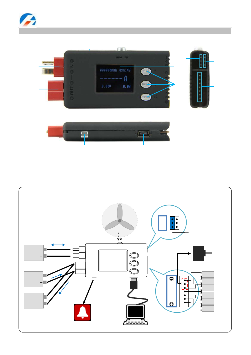
Multifunctional Monitor & Logger PowerLog 6S
External controls and connections
1. Beep
2. Input T-plug(T1) 3. Output T-plug (T2)
4. Tachometer Sensor
5. LCD screen
6. Buttons
7. Pulse I/O (J1)
8. Temperature Sensor Port (J2)
9. Multiple Voltage Input Port(J3)
10. Alarm Port
11. USB Port
⑵
⑶
⑷
⑸
⑹
⑺
⑻
⑼
⑽
⑾
⑴
PowerLog 6S Connection Diagram
RPM I/P
HOLD
MENU
s+
-
TYPE
ALM
USB
+OU
T
-
---
-
IN+
+
6
5
4
3
2
1
-
BATT.
PACK
(4.5-60V)
+
LOAD
ESC
+
POWER
charger
+
OR
Alarm
Measures RPM
Computer
or 5V Power
Temperature sensor
Pulse Input /PWM Output
1
S
+
-
J1
2
3
J2
3
2
1
PIN 7
PIN 1
1
2
3
4
5
6
1S
+
-
2S
+
-
3S
+
-
4S
+
-
5S
+
-
6S
+
-
Measures motor KV
Brushless/Brushed motor