Connecting the charger, Connect packs as shown in this diagram, Cellpro multi4 charger – ProgressiveRC Multi4 FMA Cellpro User Manual
Page 2
2
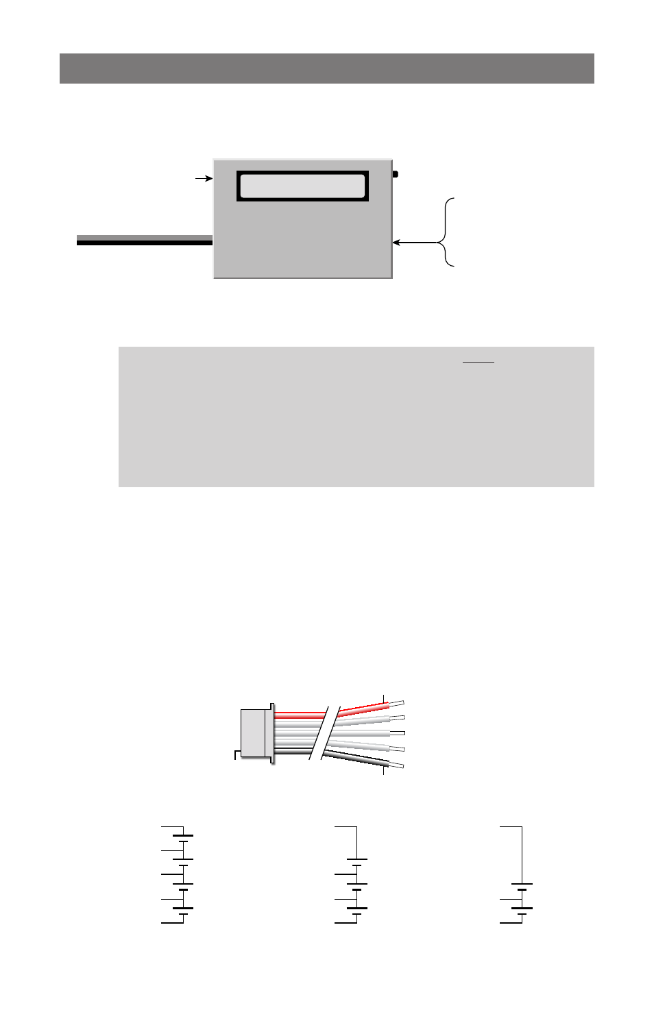
Connecting the charger
Connecting packs with a Cellpro connector
Connect packs as shown in this diagram:
Connect to 10–16 VDC
(e.g., gel cell or power supply)
Optional connection to PC
using FMA FUIM2
or FUIM3 cable
Cellpro Multi4 Charger
From pack being charged:
Node Connector*
(for balanced or unbalanced
charging)
or
Power Connector*
(for unbalanced charging)
*may require adapter
Mode
Button
Data display
To charge two packs that are connected in parallel, using two Multi4 Chargers, follow the in-
structions on page 11.
CAUTION: When two LiPo/Li-Ion/A123 packs are connected in series, do not con-
nect them to two separate chargers that are wired to a single power source. The single
power source provides a common ground to both packs, and the result is a direct short
across one of the battery packs if charging were to start. The Multi4 Charger contains
protective circuitry that prevents it from starting a charge when it detects this situation.
However,
one or both chargers, as well as the packs, could be damaged. This con-
dition can be avoided if the chargers are driven from two
unconnected power sources
(e.g., two lead acid batteries). For safest charging of series-connected packs, discon-
nect the packs from each other before connecting them to chargers.
Connecting non-Cellpro packs
FMA Direct offers plug-and-play adapters for charging LiPo/Li-Ion/A123 packs equipped
with node connectors made by other vendors. Check the Cellpro section at www.fmadirect.
com for the latest adapters.
If an adapter isn’t available for the pack you want to charge, or if the pack doesn’t have a
node connector, the FMA CPBP7 LiPo Pack Node Connector cable assembly will make the
pack compatible with the Cellpro Multi4 Charger. The diagrams below show how the Node
Connector attaches to packs of various configurations. Additional assembly information is
provided with the Node Connector.
Pin 1
FMA CPBP7 LiPo Pack
Node Connector
Red
Black
Pack positive
Node 3
Node 2
Node 1
Pack negative
Cell 4
+
–
Cell 3
+
–
Pack positive
(red), 14.8V*
Pack negative
(blk), 0V
Node 3, 11.1V*
Cell 2
+
–
Node 2, 7.4V*
4s Pack
Cell 1
+
–
Node 1, 3.7V*
Cell 3
+
–
Cell 2
+
–
Node 2, 7.4V*
3s Pack
Cell 1
+
–
Node 1, 3.7V*
Pack postive
(red), 7.4V*
Pack negative
(blk), 0V
Pack postive
(red), 11.1V*
Pack negative
(blk), 0V
Cell 2
+
–
2s Pack
Cell 1
+
–
Node 1, 3.7V*
* Nominal voltage with respect to pack negative.