4 configuration of the cmm – Kontron CP3-CMM1 User Manual
Page 7
Operating Instructions
Chassis Monitoring Module (CP3-CMM1)
31.01.2003
7
4 Configuration of the CMM
Preparations
- Switch off CMM
- Plug-in Jumper „config“ on connector X2. This
will set the CMM in the configuration mode.
- Connect the CMM to the serial port of the PC by
a 1:1 serial cable
- Start the Hyperterminal
- Settings in the Hyperterminal:
direct connection
e.g. COM1
Bit/s:
9600
Data bits:
8
Parity:
None
Stop bit:
1
Protocol:
None
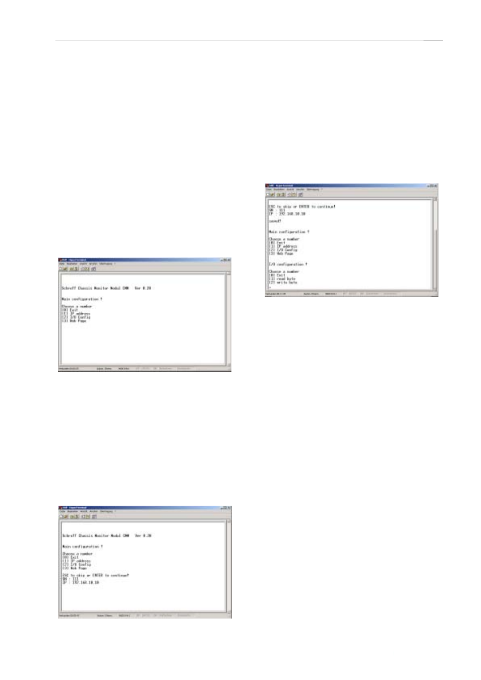
The CMM displays following Main Menu screen:
Remark: press [0] or ESC to exit a menu w/o saving
From The Main Menu you can select to enter the IP-
address, the I/O-configuration and the settings of the
html Web page.
To select any option on the Main Menu, enter the
number of the option. The program displays the
desired screen.
Set IP-Address and Serial number
Type 1 to set the IP address and the serial
number
The following screen displays:
SN = Serial Number (3-digit number): Type-in any 3-
digit number. This entry is mandatory. This number is
used to create the MAC-address of the CMM.
IP = IP-address. Enter the desired IP-address, e.g.
192.168.10.10
Type
and to return to the Main Menu. The CMM confirms it
by displaying “saved!”
I/O configuration of the CMM
The CMM display following I/O configuration
screen:
To select an option, type 1 for “Read byte” or 2 for
“write byte”:
read byte: This option allows to read the existing
CMM configuration.
Write byte: This option allows to enter a new or
modified CMM configuration
Read byte
In order to read the existing configuration, the
address of the respective parameter has to be
entered. The assignment of addresses and
parameters is described in detail in the following
chapter “Write byte”
Write byte
The following settings can be modified:
- Preset of digital outputs to “active high” or “active
low”
- Preset of digital inputs to “active high” or “active
low”
- Setting of temperature alarm thresholds
- activation/deactivation of voltage measurement
- activation/deactivation of temperature sensor
inputs
- Selection of the parameters and alarm messages
which are output via RS232
- Conjunction of Input parameters with digital
outputs
General procedure:
Enter the address given in the tables below. Then
complete the respective byte which is calculated
by replacing the “x” by “1” or “0”. Complete the
horizontal “sum” to a 8 bit binary figure.