1 functional description, 2 technical data, 3 inputs / outputs – Kontron CP3-CMM1 User Manual
Page 2: Input / output diagram
Operating Instructions
Chassis Monitoring Module (CP3-CMM1)
31.01.2003, D0.5
2
1 Functional
Description
The CMM monitors up to four different dc voltages
continuously for exceeding the high- or low-end of
voltage tolerance. An error signal is generated if
tolerance is exceeded. The error status can be displayed
by LEDs or at the HTML page. There are two additional
dc-voltage inputs available for the voltage-range +/-
24Vdc. All voltages are system ground based.
Up to seven temperature sensors can be connected
direct to the unit. Four additional temperature values are
transferred from the FCM. A temperature fail is
generated if one of the temperatures is higher than the
adjustable temperature alarm level.
There are 16 digital inputs. They can be used to identify
power-good-signals, shelf-address, VME-signals and
customized applications.
Ten digital outputs are available for customized
applications. Four signals are open-collector isolated by
opto-couplers. Six signals are TTL-compatible non-
isolated.
The CMM is able to communicate with the fan control
module (FCM). One connector ensures direct connection
to the FCM, power supply and communication. The
temperature values of FCM and the speed of fans are
transferred to the CMM.
2 Technical
Data
CMM Power Supply
Operating Voltage:
5 Vdc
Operating current approx.:
400 mA
Mechanical Dimensions
Board size:
3U x 160mm (euroboard)
Front panel size: 3U x 4HP
19”-pluggable
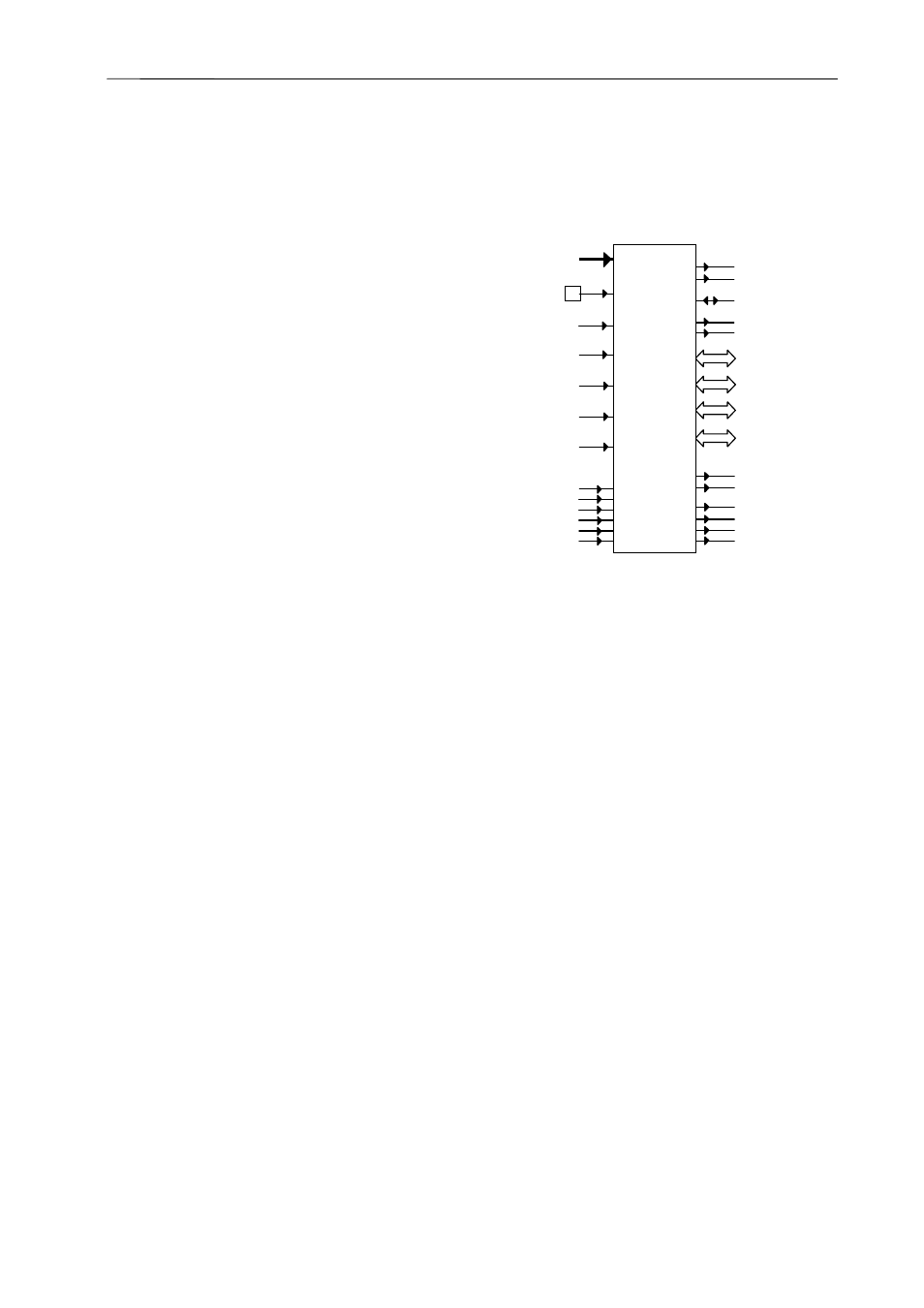
3 Inputs / Outputs
Input / Output diagram:
Input Signal Monitoring
The following signals are being monitored
continuously:
Voltage monitoring
Up to 6 DC voltages are monitored continuously.
The status of +3.3V, +5V, +12V, -12V is signaled
by the green/red LED output (within tolerance
/out of tolerance). The condition of the +24V, -
24V is signaled by default setting by digital
outputs 6 and 7 (see chapter 5).
+ 12,0
VDC
Tolerance: ± 0.6V
+ 5,0
VDC
Tolerance: ± 0.25V
+ 3,3
VDC
Tolerance: ± 0.25V
– 12,0
VDC
Tolerance: ± 0.6V
+ 24,0
VDC
Tolerance: ± 2.4V
– 24,0
VDC
Tolerance: ± 2.4V
NTC temperature sensors
Up to 7 NTC temperature sensors can be
connected to the CMM. The number of
connected NTCs must be registered manually
in the configuration mode of the CMM (see
chapter 5). Two temperature alarm thresholds
(20°C...70°C) can be set. If the CMM is
connected to the FCM, the NTC with the highest
temperature reading of both modules gives the
fan speed.
υ
NTC [1..7]
+3.3V monitor in
+12V monitor in
-12V monitor in
+5V monitor in
+24V monitor in
-24V monitor in
+5V Module power
Voltage ok/fail + 5V LED red/green
Voltage ok/fail +3.3V LED red/green
Voltage ok/fail +12V LED red/green
Voltage ok/fail –12V LED red/green
Fan Fail LED red
Over Temp LED red
Shelf address [A0..A4] (CPCI)
PSU derating [1..4] (CPCI)
PSU-fail [1..4] (CPCI)
AC-fail [1..2] (VME)
SYSRESET (VME)
DEG (CPCI) / AC-Fail (VME)
Opto coupler output [1..4]
TTL-output [1..4]
FAL (CPCI)
RS232 (front panel)
RS485
Ethernet 10BaseT, (front panel)
Data bus to FCM
SYSFAIL (VME)