Kontron CP3-CMM1 User Manual
Page 6
Operating Instructions
Chassis Monitoring Module (CP3-CMM1)
31.01.2003
6
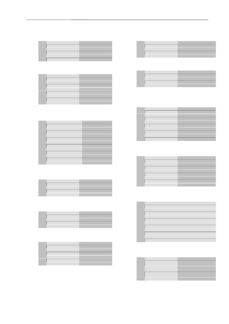
X11:
RS232 interface
D-Sub DIN 41652 9pin female
Pin
type
Name
Description
5
GND
Ground
2
TxD
RS232: TxD
8
CTS
RS232: CTS
3
RxD
RS232: RxD
7
RTS
RS232: RTS
X12:
RJ 45 Ethernet
8pin RJ 45
Pin
type
Name
Description
1
Eth Tx+
Ethernet TransmitA
2
Eth Tx-
Ethernet TransmitB
3
Eth Rx+
Ethernet ReceiveA
4
GND
Ground
5
GND
Ground
6
Eth Rx-
Ethernet ReceiveB
7
GND
Ground
8
GND
Ground
X20:
Connector for LED display
Male connector: 2,54 mm grid 12pin
Pin
type
Name
Description
1
out
+3V3 anode gr
LED +3.3V green anode
2
out
+3V3 anode re
LED +3.3V red anode
3
out
+5V anode gr
LED +5V green anode
4
out
+5V anode re
LED +5V red anode
5
out
+12V anode gr
LED +12V green anode
6
out
+12V anode re
LED +12V red anode
7
out
-12V anode gr
LED -12V green anode
8
out
-12V anode re
LED - 12V red anode
9
out
FanFail anode re
LED FanFail red anode
10
out
TempFail anode re
LED TempFail red anode
11
out
GND
Ground
12
out
GND
Ground
X22: Temperature
connector
Tyco 640456-4 4pins
Pin
type
Name
Description
1
In
Temp 1+
connection NTC pin1
2
In
Temp 1-
connection NTC pin2
3
In
Temp 2+
connection NTC pin1
4
in
Temp 2-
connection NTC pin2
X23: Temperature
connector
Tyco 640456-4 4pins
Pin
Name
Description
1
In
Temp 3+
connection NTC pin1
2
In
Temp 3-
connection NTC pin2
3
In
Temp 4+
connection NTC pin1
4
in
Temp 4-
connection NTC pin2
X24:
FCM connector 6pin
Molex 39-28-1063
Pin
type
Name
Description
2
I2C/SDA
CMM-Bus-SDA
1
I2C/SCL
CMM-Bus-SCL
3
I2C/GND
CMM-Bus-GND
6
+5V aux
Power supply input
4
Vcc (+5V)
Power supply input
5
GND
Ground
X25: RS485
interface
Molex 43045-0418 4pins
Pin
type
Name
Description
1
RS485 Rx+
RS485: Receive A
2
RS485 Rx-
RS485: Receive B
3
RS485 Tx+
RS485: Transmitt A
4
RS485 Tx-
RS485: Transmitt B
X26: Signals-Input
Molex 43045-0418 4pins
Pin
type
Name
Description
1
In
DIN14/ AC-fail1
Digital input 14 / default
2
in
DIN15/ AC-fail2
Digital input 15 / default
3
GND
Ground
4
GND
Ground
X27: Signals-Input
Male connector: 2,54 mm grid 2*7pins
Pin
type
Name
Description
1
In
DIN1 / FALin1
Digital input 1 / default
2
In
DIN2 / FALin2
Digital input 2 / default
3
In
DIN3 / FALin3
Digital input 3 / default
4
In
DIN4 / FALin4
Digital input 4 / default
5
In
DIN5 / DEGin1
Digital input 5 / default
6
In
DIN6 / DEGin2
Digital input 6 / default
7
In
DIN7 / DEGin3
Digital input 7 / default
8
in
DIN8 / DEGin4
Digital input 8 / default
12
GND
Ground
X28: Signals-Input
Molex 43045-0818 8pins
Pin
Name
Description
7
+5V aux
Power supply input
8
GND
Ground
1
In
+12V (V3) in
+ 12V voltage monitor input
2
In
+5V (V2) in
+ 5V voltage monitor input
3
In
+3.3V (V1) in
+ 3.3V voltage monitor input
4
In
-12V (V5) in
- 12V voltage monitor input
5
In
+24V (V4) in
+ 24V voltage monitor input
6
in
-24V (V6) in
+ 24V voltage monitor input
X29:
Utility connector 12pin
Erni 063 179
Pin
type
Name
Desciption
A3
GND
Ground
A4
In
+12V (V3) in
+ 12V voltage monitor input
B3
In
+5V (V2) in
+ 5V voltage monitor input
B4
In
+3.3V (V1) in
+ 3.3V voltage monitor input
B5
In
-12V (V5) in
- 12V voltage monitor input
A1
In
DIN0 / SYSFAIL
Digital input 0 / default
B1
In
SYSRESET
VME SYSRESET signal
A2
out
OUT8 / DEG_out
Digital output 8 / default
B2
out
OUT9 / FAL_out
Digital output 9 / default
A5
In
DIN1 / FALin1
Digital input 1 / default
A6
In
DIN2 / FALin2
Digital input 2 / default
X30: Signals-Output
Molex 43045-0418 4pins
Pin
type
Name
Description
1
out
OUT4 / AC-
fail_out
Digital output 4 / default
2
out
OUT5 /
SYSFAIL_out
Digital output 5 / default
3
out
OUT6 / +24V (V4)
failure
Digital output 6 / default
4
GND
Ground