Outputs signals – Kontron CP3-CMM1 User Manual
Page 3
Operating Instructions
Chassis Monitoring Module (CP3-CMM1)
31.01.2003, D0.5
3
Digital Inputs
16 freely selectable digital input signals.
The following table shows the default assignment
of the digital inputs. This assignment and status
(active low/high) can be modified in the
configuration mode of the CMM (see chapter5).:
Input
Default
R96
pin
Default assigned
to
User defined
assignement
possible
DIN0
SYSFAILin
A9
SYSFAIL_out /
OUT5
Yes
DIN1
FALin1
C2
DIN2
FALin2
C3
Yes
DIN3
FALin3
C4
DIN4
FALin4
C5
FAL_out / OUT9
OR-wired
Yes
DIN5
DEGin1
C6
Yes
DIN6
DEGin2
C7
Yes
DIN7
DEGin3
C8
Yes
DIN8
DEGin4
C9
DEG_out / OUT8
OR-wired
Yes
DIN9
HA_A0
C15
No
DIN10
HA_A1
C16
No
DIN11
HA_A2
C17
No
DIN12
HA_A3
C18
No
DIN13
HA_A4
C19
No assignment to
digital output
No
DIN14
AC-fail1
C11
DIN15
AC-fail2
C12
AC-fail_out / OUT4
OR-wired
Yes
SYSRESET digital Input
The SYSRESET is connected as Input/Output. In
the Input mode it can be assigned to switch a digital
output.
Outputs Signals
LED display
6 LEDs can be directly connected to the LED
outputs:
4 two colored LEDs (red/green), for +3.3V, +5V,
±12V OK/out-of-tolerance indication.
2 red LEDs for fault indication of “Fan Fail” and
“Temp Fail” signals (fail=LED on, OK=LED off)
There are no LED’s or other optical or acoustic
signal indicators mounted on the front panel or
the module itself.
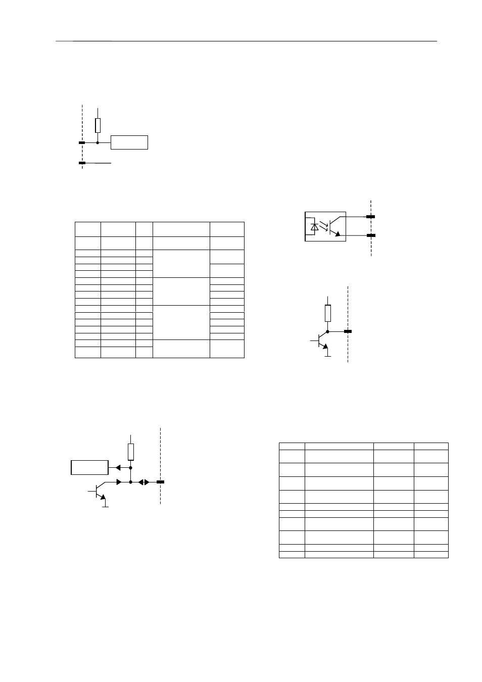
Digital Outputs
10 digital output signals are available:
•
4 open-collector output signals isolated
by opto-couplers:
•
6 TTL-compatible non-isolated signals:
The following table shows the default
assignment of the digital outputs. This
assignment and status (active low/high) can be
modified in the configuration mode of the CMM
(see chapter5).
output
Default-assignment
Type
R96 pin
OUT0
Braking of sensor wire
Optocoupler
Output
A13 / A14
OUT1
Temperature failure
CMM
Optocoupler
Output
A15 / A16
OUT2
Temperature failure
FCM
Optocoupler
Output
A17 / A18
OUT3
Fan Fail_out
Optocoupler
Output
A19 / A20
OUT4
AC-fail_out
TTL-Output
A22
OUT5
SYSFAIL_out
TTL-Output
A23
OUT6
V5 (+24V) out of
tolerance
TTL-Output
A24
OUT7
V6 (-24V) out of
tolerance
TTL-Output
A25
OUT8
DEG_out
TTL-Output
A11
OUT9
FAL_out
TTL-Output
B27
TTL-Input-
Logic
+5V
10k
GND
+
5V
10k
SYSRESET
TTL-Input-
Logic
High impedance = 1
Low impedance = 0
+5V
10k
+5V = 1
GND = 0