14 spi connector (j32), Spi connector (j32) – Kontron KTQM87-mITX User Manual
Page 44
KTD-N0886-A
Page 42
Internal Connectors
KTQM87/mITX Users Guide
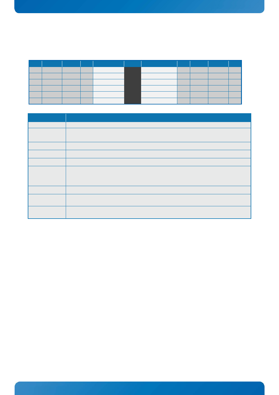
SPI Connector (J32)
7.14
The SPI Connector is normally not used. If however a SPI BIOS is connected via the SPI Connector then the
board will attempt to boot from it.
Note Pull U/D Ioh/Iol Type
Signal
PIN
Signal
Type Ioh/Iol Pull U/D Note
1
-
CLK
1 2
SB3V3
PWR
-
-
-
I
CS0#
3 4
ADDIN
IO
/10K
10K/
-
NC
5 6
NC
-
-
-
10K/
IO
MOSI
7 8
ISOLATE#
IO
100K
-
IO
MISO
9 10
GND
PWR
-
-
1K
IO SPI_IO2_#WP
11 12
SPI_IO3_#HOLD IO
1K
Signal
Description
CLK
Serial Clock
SB3V3
3.3V Standby Voltage power line. Normally output power, but when Motherboard is
turned off then the on-board SPI Flash can be 3.3V power sourced via this pin.
CS0#
CS0# Chip Select 0, active low.
ADDIN
ADDIN input signal must be NC.
MOSI
Master Output, Slave Input.
ISOLATE#
The ISOLATE# input, active low, is normally NC, but must be connected to GND when
programming the SPI flash. Power Supply to the Motherboard must be turned off when
loading SPI flash. The pull up resistor is connected via diode to 5VSB.
MISO
Master Input, Slave Output
SPI_IO2_#WP
SPI Data I/O: A bidirectional signal used to support Dual IO Fast Read, Quad IO Fast Read
and Quad Output Fast Read modes. The signal is not used in Dual Output Fast Read mode.
SPI_IO3_#HOLD SPI Data I/O: A bidirectional signal used to support Dual IO Fast Read, Quad IO Fast Read
and Quad Output Fast Read modes. The signal is not used in Dual Output Fast Read mode.