ISSPRO R72022 User Manual
Page 2
Form No. IS192 (Rev. A 04/15/2009)
ISSPRO, INC.
2515 N.E. Riverside Way
Post Office Box 11177
Portland, Oregon 97211-1899
503-288-4488
800-888-8065
Fax: 503-249-2999
www.isspro.com
© 2008 ISSPRO, Inc. All Rights Reserved.
5
The harness dimmer input (orange wire with black stripe) can be connected three ways:
Option A – Dimming with the factory dimmer circuit, but allowing the potentiometer to adjust
the EV² gauge brightness below the level of the factory dimmer. In other words, the gauges will
still dim when the factory dimmer is turned down, but the gauge potentiometer can turn the
gauges down lower. The gauges are normally slightly brighter than factory dash lighting at any
given dimmer setting. For this option, connect the orange/black wire to a factory dimmer circuit
(one which outputs battery voltage when the dimmer is at full brightness, and reduced voltages at
lower lighting levels). This circuit may be found at the back of the headlight switch, or possibly
through a fuse in the fuse panel. Check the vehicle wiring diagrams to confirm.
Option B – Dimming independently from the factory dimmer circuit, but still turning on and off
with the vehicle lights. The potentiometer knob on this harness will control the brightness of the
gauges, but they will still turn off when the vehicle's lights are off. Connect the orange/black wire
through an inline fuse (max 3 amps) to a light output from the vehicle's headlight switch. Find a
circuit that is powered only when the vehicle's marker/parking lights are on.
Option C - Dimming independently from the factory dimmer circuit, with the gauge lights on any
time the vehicle is on. The potentiometer knob on this harness will control the brightness of the
gauges, including turning them off, but they will otherwise turn on and off with the vehicle
ignition. Connect the orange/black wire to the same ignition circuit as the red wire from step 2.
6
Install the sensor wires for each gauge per the individual
gauge instructions.
7
Route the longer length of red and black wires, plus the
orange wire, to the first gauge location. If using the ISSPRO
wire insertion tool (R72023), follow the instructions with the
tool. Otherwise, use a small flat-blade screwdriver. Install the
three wires into the insulation displacement connector (orange
connector). Carefully lay the wires across the connector
cavities, hold the connector steady with a vice or pliers and
press the wires into each cavity with the screwdriver. Press
initially in the center portion of the wire as it goes into the
connector, and then push down on each side of the wire
(along the edge of the connector). Each wire must be pushed
completely to the bottom of its groove in the connector to
ensure a good electrical connection.
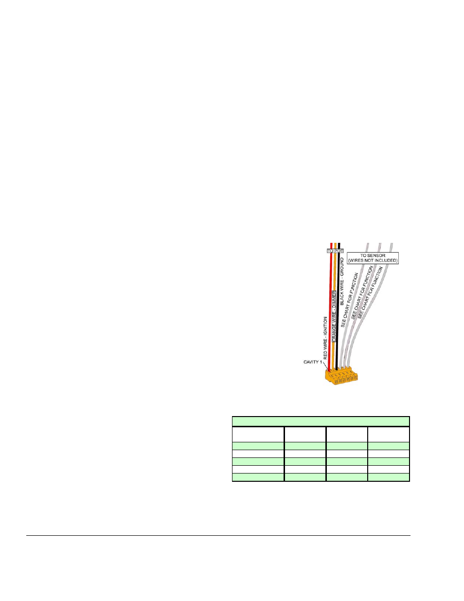
Figure 2. Connector with long wires.
See Sensor Wire Pin Out Table below:
8
Route the red, orange and black wires to the
next gauge connector in line and repeat step 7
above.
GAUGE TYPE
CAVITY 4
FUNCTION
CAVITY 5
FUNCTION
CAVITY 6
FUNCTION
PYROMETER
SENSOR (+)
SENSOR (-)
GROUND
TEMPERATURE
NOT USED
SENSOR
GROUND
PRESSURE
+ 5 VOLTS
SENSOR
GROUND
VOLTMETER
NOT USED
IGNITION
NOT USED
FUEL LEVEL
NOT USED
SENSOR
GROUND
SENSOR WIRE PIN OUT