ISSPRO R8588M User Manual
ISSPRO Measuring instruments
ISSPRO, INC. 2515 N.E. Riverside Way, Portland OR 97211
Telephone: (503) 288-4488 Toll Free: (800) 888-8065
FAX: (503) 249-2999
Form IS128 (Rev C 12/02/2010) Page 1 of 4
ISSPRO 3 3/8” PROGRAMMABLE TACHOMETER
Microprocessor Version
GENERAL INFORMATION:
Operating Voltage:
11 - 30 VDC: NOTE - Instrument comes equipped with a 12V lamp. Replace lamp
with one of proper voltage when installing instrument on 24V systems. 24V Lamp Part # is GE-656
Input:
Gear tooth sensor, AC generator, alternator tap.
Programmable Range: 1-255 pulses per engine revolution (gear teeth, magnets, etc).
Transient Protection: +100 V, -400 V
Reverse Voltage Protected
Hourmeter (optional): Operates only when engine runs
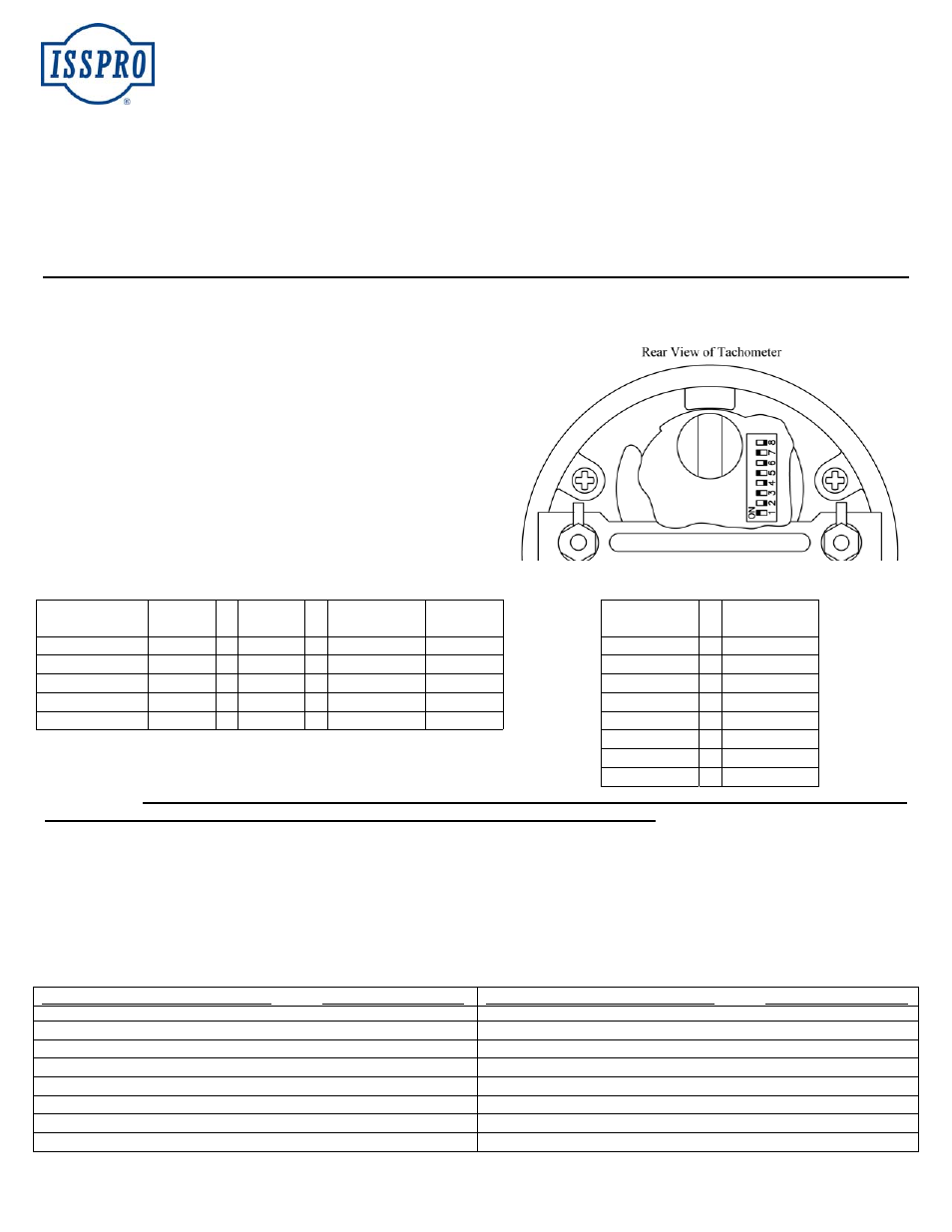
CALIBRATION PROCEDURE:
Remove the hole plug by pressing above the center enough to allow a
small coin, screwdriver, etc., to be inserted in the slot behind the upper
edge. Twist to remove.
Each of the eight switches has a different value as shown in the table at
the right. Add the switch values to equal the number of pulses per
engine revolution. These switches will be set “on”. All others will be
off. NOTE: The switch setting must be done with the power “OFF”.
If power is left “ON”, changing the switch setting will have no effect on
calibration until the power is interrupted.
Example: Find switch numbers by subtracting the switch value from
the remaining number. Always use the largest value that can be
subtracted from the remainder for each successive step. For example,
set the following switches “on” for a gear with 103 teeth:
Switch
Value
New
Remainder
Switch
Number
Switch
Value
Start: 103 - 64 = 39
#7
#1
=
1
Remainder
of: 39 - 32 = 7
#6
#2 = 2
Remainder
of: 7 - 4 = 3
#3
#3 = 4
Remainder
of: 3 - 2 = 1
#2
#4 = 8
Remainder
of: 1 - 1 = 0
#1
#5 = 16
#6 = 32
Or use the calibration chart provided (pages 3 and 4)
#7
=
64
#8
=
128
IMPORTANT! When changing switch settings on an installed tach, the power to the unit must be cycled either by turning the
ignition switch off and then back on, OR by momentarily disconnecting the “hot” (red) wire.
SIGNAL GENERATOR (Sender Unit): Generator is installed on tachometer cable drive of engine: NUMBER OF PULSES PER
REV = (Number of sender pulses per turn) X (Ratio of take off RPM to engine RPM). NOTE: If the number of pulses per revolution
(from equation) is not a whole number, the tach will not be accurate. In this case, select a generator so that this number is non-fractional.
EXAMPLE: The number of sender pulses per turn is 15, and the take off ratio is 0.5 to 1 (.e. cam drive).
Number of Pulses per Rev = 15 x 0.5 = 7.5. This will result in an error in the tachometer reading. Select a sender with an even number of
pulses per turn (e.g. ISSPRO R8970). The number of pulses per revolution will then be a whole number, in this case, 15.
FREQUENTLY USED SENDERS
# PULSES PER REV
FREQUENTLY USED SENDERS
# PULSES PER REV
DATCON 4-D-C 71267
8
SUN CP7643
6
DIXSON SG201A, SG201A1, SG202
2
SYNCHRO-START Minigen
30
ENGLER 870-0588
15
TELEFLEX 9604276
8
ISSPRO R8970, R8940
30
VDO (Old Style Engler) ISSPRO 300092
4
KIENZLE-ARGO 8-161-237008
8
ZEMCO 4710
8
MOTOROLA 4-100 (7SG100), 4-111 (7SG100B)
30
ZEMCO 6314
5
ROCKWELL 240R02-001
30