ISSPRO R8480 User Manual
ISSPRO Hardware
ISSPRO, INC. 2515 N.E. Riverside Way, Portland OR 97211
Telephone: (503) 288-4488 Toll Free: (800) 888-8065
FAX: (503) 249-2999
Form No. IS073 (6/21/01 Rev. B) Page 1 of 4
ISSPRO 3 3/8” Dia. Programmable Speedometer
Aircore Version
General Information:
Operating Voltage:
11-30 VDC: NOTE – Instrument comes equipped with a 12V lamp. Replace lamp with one of proper
voltage when installing instrument on 24V systems.
Input: Magnetic sensor or AC generator
Transient Protection: +100 V, -400 V
Reverse Voltage Protected
Calibration:
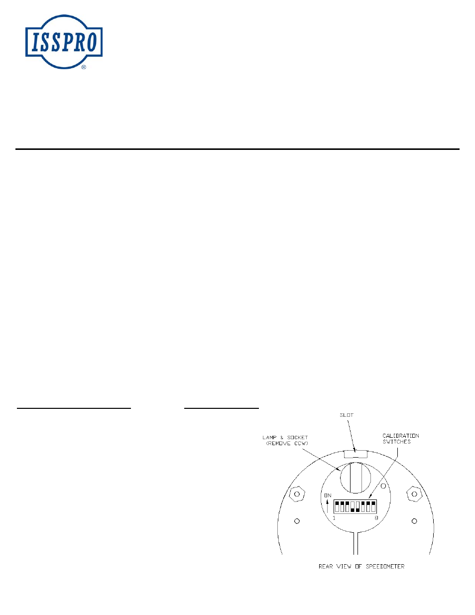
The ISSPRO Programmable Speedometer is calibrated (programmed) by setting a combination of eight switches found in the rear of the
instrument. The odometer and pointer are electronically linked together and both are calibrated when the switches are properly set. Program
before installing. Models are available with and without odometers.
Calibration Procedure:
Calculate the “calibration number” from the appropriate formula below. (A minimum calibration number of 9531 is required to be within
calibration range). Refer to the “CALIBRATION SWITCH SETTING” table with this number. Locate the row in which the calibration
number is between the limits, then set the switches marked with an “X” to the “on” position (up).
EXAMPLE: Calibration number = 43620: From the table 43620 lies between 43250 and 43900, therefore, switches 1,2,3,6,7 and 8 will be
set to “on”.
(1) Front wheel mounted tone wheel: CALIBRATION NUMBER = # SLOTS IN TONE WHEEL X TIRE REVS PER MILE
(2) Tail Shaft mounted magnetic sensor: CALIBRATION NUMBER = TIRE REVS PER MILE X DIFFERENTIAL RATION X 16
(3) Sender driven from transmission cable drive:
CALIBRATION NUMBER = CABLE TURNS PER MILE (Usually 1000) X PULSES PER SENDER TURN
If the # of cable turns per mile is not known, follow this procedure: Obtain a ratio tester and a correct drive tang for your transmission. With
a steel tap measure, mark off 1/10
th
mile (528 ft.) in as straight of a line as possible. Mark start and stop lines with chalk or paint. Position
the vehicle so that one of the wheels aligns with the start mark. Disconnect the speedometer cable at the transmission and install the ratio
tester in its place. Secure the cables and reset the ratio tester. Drive the vehicle to the stop point positioning the selected wheel on the stop
mark. The reading displayed on the ratio tester is the number of cable turns per mile if using and Engler “SAC-10”. If using an SS White
ratio tester (P/N 312-12175Y), multiply the reading by 10 to obtain the cable turns per mile.
FREQUENTLY USED SENDERS
#PULSES PER TURN
DATCON 4-D-C 71267
8*
DIXSON SG201A, SG201A1, SG202
2*
ENGLER 870-0588
15
ISSPRO R8970, R8940
30
KIENZLE-ARGO 8-161-237008
8*
MOTOROLA 4-100 (7SG100), 4-111 (7SG100B)
30
ROCKWELL 240R02-001
30
SUN Model CP7643
6*
SYNCHRO-START Minigen
30
TELEFLEX 9604276
8*
VDO (Old Style Engler) ISSPRO 300092
4*
ZEMCO 4710
8*
ZEMCO 6314
5*
*NOTE: These senders do not produce the minimum required # of pulses
to be in calibration range when driven at 1000 turns per mile. It may be
necessary to change your sender to one that generates more pulses per rev
such as an ISSPRO R8970.