Please read entire directions before starting – ISSPRO R8480-SET User Manual
Page 8
ISSPRO, INC. 2515 N.E. Riverside Way, Portland OR 97211
Telephone: (503) 288-4488 Toll Free: (800) 888-8065
FAX: (503) 249-2999
Form IS118 (Rev D 2/18/09) Page 1 of 1
Odometer/Hourmeter Setting Instructions
For Tachometers and Speedometers with Counter Access Slot
Access to the counter enables setting of mileage or engine hours in the field
. The user is responsible to insure that all laws and
regulations are complied with when setting the odometer mileage
. Normally, mileage can only be legally set to actual vehicle
mileage when replacing the speedometer or in Heavy Duty applications such as Class 8 trucks. ISSPRO is not responsible for any
liabilities associated with the setting of mileage on this unit in the field. Damage caused to the speedometer or tachometer by setting the
counter is NOT covered by the ISSPRO warranty.
**** Please read entire directions before starting. ****
The speedometer or tachometer is shipped with a yellow warning label covering the counter access slot. An additional label is supplied to
re-cover the slot after the counter has been set. To set the counter:
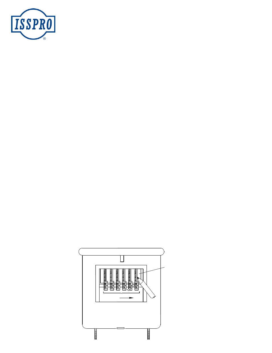
1.
Remove the warning label from the unit covering the slot.
For instruction purposes, setting the odometer is shown. An hourmeter should only need the numbered wheels changed.
2.
Determine the mileage setting that you want to enter on the odometer. For this example, we will assume that the mileage
on the speedometer that is being replaced as 45,567 miles.
3.
Begin from the right side of the counter and set the 1-mile odometer wheel first. To do this, carefully slide idler gear #1 to
the right (towards the tenth wheel) with a small flat blade screwdriver or similar tool. Be careful not to damage the idler or
odometer wheel. Use only enough pressure to disengage the idler from the ODO wheel. When the gear has been moved
far enough, it will disengage from the odometer wheel and allow you to turn the odometer wheel to the desired setting
(Number 7 in this example), with another tool, such as a toothpick or a pencil. Do not allow the idler gear to turn on its
shaft. Note: All of the idlers must have alternating long and short teeth lined up across the counter before and after the
setting. Release the idler from the pressure applied by the screwdriver and allow it to reengage the odometer wheel teeth.
Make sure that the digit that has been set is lined up correctly in the face dial window and that lower digits are aligned
correctly.
4.
Proceed to the left and set each odometer wheel in succession until all digits have been set. In this example, set the “7”
and move to the “6”, then “5”, then “5”, then “4”. Double check to make sure that the correct mileage number is shown in
the face dial window and correctly lined up. Also, check the large and small teeth of the idler gears to make sure that they
have not shifted and are also lined up. You may now do a simple test to insure that the odometer will operate correctly.
By viewing the unit from the front at a steep angle, a dull metal plate can be seen underneath the idler gears . If you
carefully insert your small screwdriver through the slot and tap this plate several times in succession, the odometer should
begin to count at each tap of the plate.
5.
Make sure that no foreign objects have fallen into the unit then re-cover the access slot using the extra warning label
provided.
0 4 5 5 6 7
#6
#5
#4
#3
#2
#1
Push idler gears with
small screwdriver
Rotate ODO wheel(s) with
pencil or pen while pushing
idler gears to disengage
teeth.
Diagram is not actual size
Digits shown as example
only. Number is visible
through front glass.