ISSPRO R4901A User Manual
Page 2
Form No. IS078 (11/8/07 rev C) Page 2 of 2
Reverse Voltage Protection:
12 V units: -12 VDC indefinitely, -400 V transients
24 V units: -24 VDC indefinitely, -400 V transients
All units are standard non-latched.
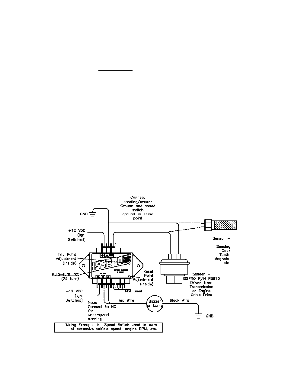
Adjusting the Trip Point:
The R4901A can be adjusted with a small screwdriver. Remove the cover to access the adjustment. See diagram
for location of adjustment screw. PLEASE NOTE: There is a (25 turn) multi-turn pot. Turning pot counter
clockwise (CCW) increases the speed setting (Hertz Trip Point) and CW decreases the speed setting. Check
operation after adjustment to ensure correct operation turning CW decreases the speed setting. Check after
adjustment to ensure correct operation. The best method is to use a signal generator (if available) to supply the
desired trip frequency, and then adjust the Multi – Turn Pot until the relay trips. You can tell if the relay trips by
using an ohmmeter, a test light or just listening for it. In many cases, a signal generator is not available. In these
cases, simply install the unit and run the vehicle or engine at the desired trip point. Then adjust the screw until the
relay trips. Close the unit to complete your installation. Retest for correct set point and operation.
Adjusting the reset point (Hysteresis):
Hysteresis is the difference between the trip point and the reset point on non-latched units. An example would be
that the trip point is 55 MPH but hysteresis is adjusted so that the unit resets at 50 MPH. To adjust the Hysteresis,
first apply a frequency to trip the unit. Reduce the frequency to where you want the unit to reset. Carefully adjust
the Reset Point Adjustment, single turn, pot slightly until the unit resets then re-test. Turn CW to lessen the amount
of Hysteresis and CCW to increase hysteresis.
Installation Hints:
(1) Unit is not sealed…mount in cab, away from harsh environments.
(2) Ground the enclosure to help shield against CB or other radio interference.