ETS-Lindgren 2175 Antenna Tower User Manual
Page 24
24
|
Assembly and Installation
The branch circuit supplying power to the motor base should be protected from
excess current according to local electrical codes. Whenever possible the motor
should be powered from a separate branch circuit of adequate current capacity to
keep voltage drop to a minimum during startup and running.
Check that the conductor size is adequate for the motor load and the distance
from the mains source. Improperly sized conductors will lead to a high voltage
drop in the power conductors and cause reduced starting torque and premature
motor failure. For longer runs, increase the wire size in accordance with the wire
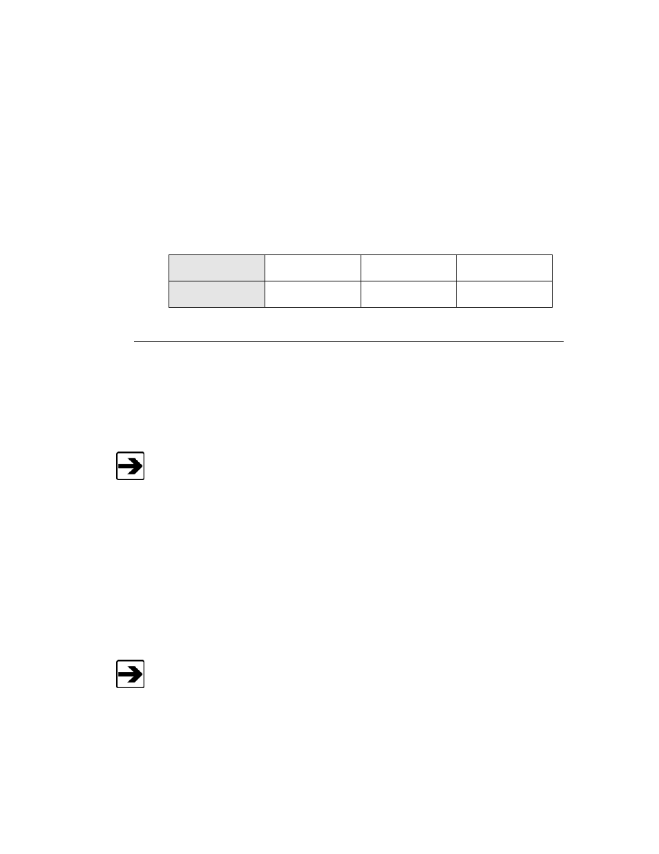
selection guide shown below. When considering what gauge of wire to use,
never use smaller than 14 AWG for any installation.
Length of wire
@220V
0–15.24 m
(0–50 ft)
15.24–30.48 m
(50–100 ft)
30.45–60.96 m
(100–200 ft)
Wire gauge
required
14 AWG
14 AWG
14 AWG
Connecting the Controller
Any combination of devices may be connected to the two device interface ports
located on the rear panel of the Model 2090 Multi-Device Controller (or next
generation ETS-Lindgren controller, if applicable). The default settings are for a
tower connected to the Device 1 interface port and a turntable connected to the
Device 2 port.
Fiber optic cabling for each device should not be allowed to hang unsupported
from the rear panel of the controller. The fibers and connectors are easily
broken if twisted or bent. Keep the fiber optic cables as straight as possible
from the connector to the protective sheath.
Device connection is accomplished with a dual fiber optic cable included with the
device. This cable terminates into two ST connectors that are identical at both
ends. The cable is symmetrical; either end can be connected to the controller. A
fiber optic cable that connects to the IN port of a controller should, at the other
end, be connected to the OUT port of the motor base. A fiber optic cable
connected to the OUT port of the controller should, at the other end, be
connected to the IN port of the motor base.
The fiber optic mechanical limits must be set before the carrier is able to move.