Test, Parts list, Circuit details – Elecraft Ngen User Manual
Page 2: Caution
Page 2 of 2
Test
CAUTION
: Whenever you use the N-gen with a transceiver, you must prevent accidental transmit, which could damage
parts on the N-gen. Disconnect all keying devices (key, paddle, microphone). Reduce the transceiver's power level to the
lowest possible. In the case of a K2, rotate POWER fully counter-clockwise.
Install a standard 9-volt battery into the battery holder.
If you plan to test the N-gen using a transceiver, disable transmit as described above.
Connect the N-gen to the antenna input of a receiver or transceiver.
Place SW1 in the “ON” position.
The LED should light and there should be a substantial increase in the noise output of the receiver.
Parts List
Note: Resistor color codes and typical capacitor markings are shown in parentheses.
R1, 200 ohms 1/4 watt (red, black, brown)
R4, 47 ohms 1/4 watt (yellow, violet, black)
R2, 150 ohms 1/4 watt (brown, green, brown)
R5, 560 ohms 1/4 watt (green, blue, brown)
R3, 1000 ohms 1/4 watt (brown, black, red)
D1, D4, 1N4148
C1, C2, .01uF mono ceramic (103)
D2, 1N5235B
C3, .047uF mono ceramic (473)
D3, Red LED
C4, 10 pF ceramic (10J or 100)
U1, MAR-1 MMIC
S1, Miniature DPDT Switch
(2) 4-40 pan-head machine screw
J1, 12 volt power connector
(2) lock washer
J2, BNC output connector
(2) 4-40 nut
J2, BNC output connector
(4) rubber feet
N-gen PC board
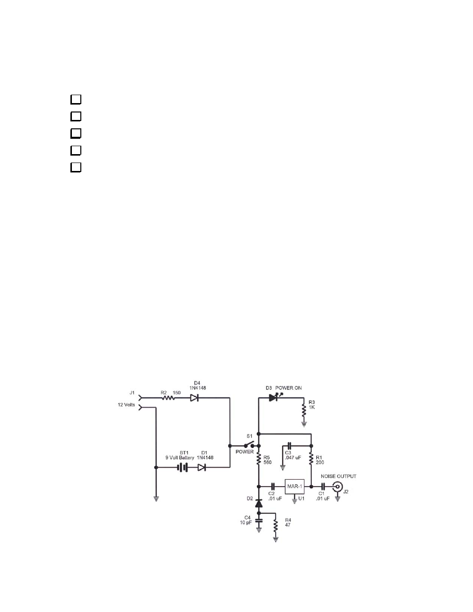
Circuit Details
The schematic of the N-gen is shown above. Noise generated within Zener diode D2 is amplified by wideband monolithic
amp U1. U1 is internally biased to present a 50-ohm load at the output.