Elecraft XV Bypass Capacitor Change User Manual
Elecraft Accessories communication
Elecraft • www.elecraft.com • 831-662-8345
Elecraft XV Transverter Builder’s Alert
Bypass Capacitor Change
Revision B, April 30, 2009
Copyright © 2009, Elecraft, Inc. All Rights Reserved
We recently discovered that the XV50, 144, 222 and 432 transverters may experience erratic behavior under
certain conditions. There are two causes: RF energy entering voltage regulator U4, and voltage surges on the 5V
bus caused by the relay coils.
Even if you have not experienced any erratic behavior of your transverter, we strongly advise you make these
modifications to ensure stable operation under all conditions. They involve adding three leaded parts. You need
only remove the top cover.
You will need the following parts available from Elecraft. If you received this Builder’s Alert with your
transverter kit, the parts are included in your kit along with instructions about when to install them. See the errata
sheet supplied with your Assembly manual.
Quantity
Description
Elecraft Part Number
2
Capacitor, monolithic, 0.1 uF (104),50V,20%,0.1” lead spacing
E530020
1
Capacitor, electrolytic, 10 uF,16V,20%, 0.1” lead spacing
E530142
Procedure
Disconnect power from your transverter, remove the top cover four corner screws and remove the
cover.
Observe ESD precautions when inside your transverter. Wear an ESD wrist strap or
frequently touch an unpainted metal ground while working.
Locate voltage regulator U4. It is just behind the front panel with a heat sink tab bolted to the pc
board.
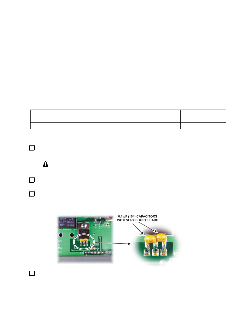
Install the two 0.1 µF (104) capacitors between U4’s center and outer pins as shown below. Solder
the capacitors directly the U4’s pins with very short leads. Hint: Bend the capacitor leads and hold them
with your pliers while tacking one lead onto U4 with your soldering iron carrying a small drop of solder.
Then solder the other lead, clean up the first connection if needed, and trim off the excess leads.
Check the resistance between the center pin and each outside pin using your DMM. It must be greater
than 500 ohms to confirm no shorts between U4’s pins.
(OVER)