Elecraft KPA100UPKT Errata User Manual
Page 2
Page 2
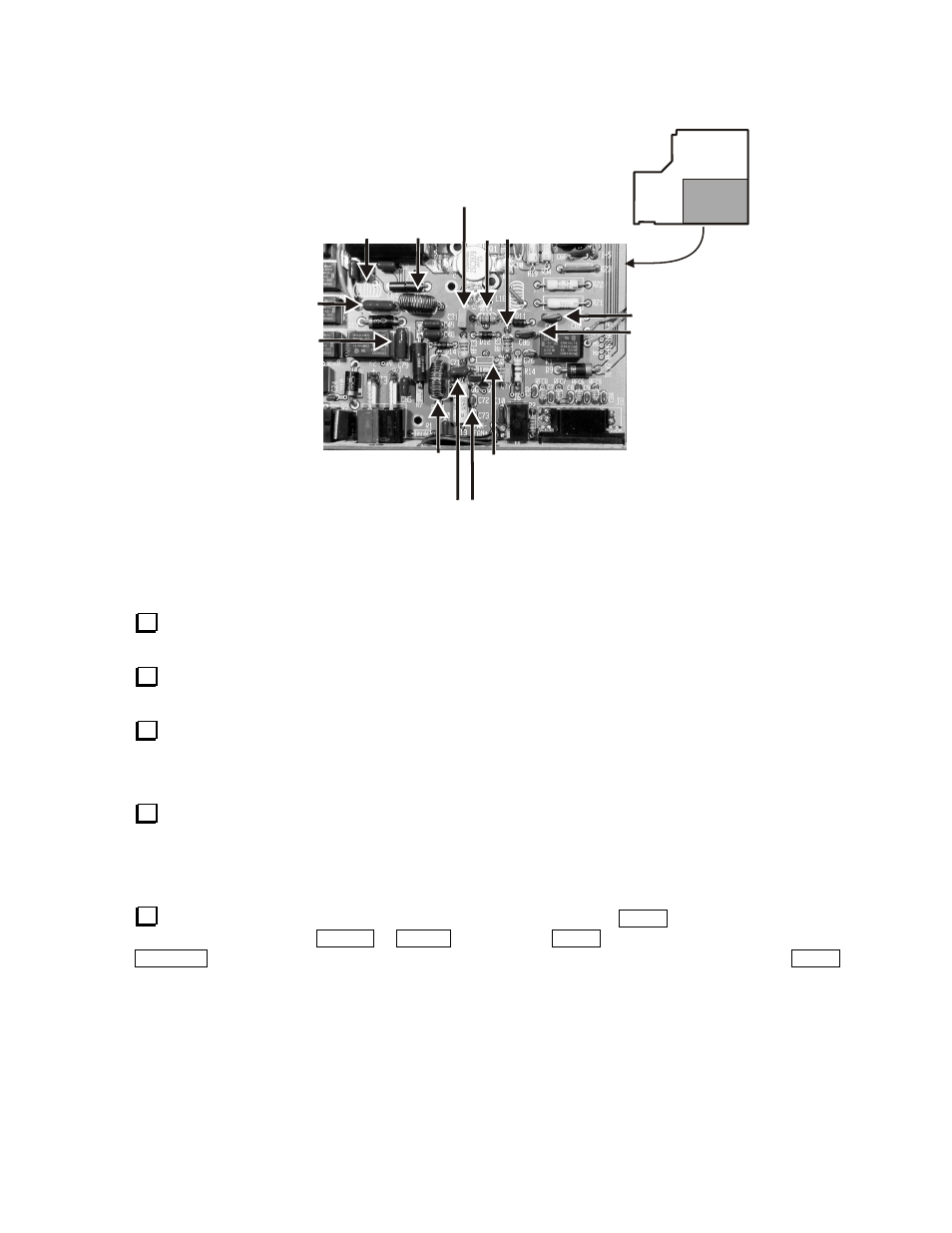
7. Page 6, Figure 5: Cut out the new figure 5 below and paste it over figure 5 in the manual.
C67 - .0047 µF 100V
C64 - .0047 µF 250V
C31 - .22 µF
C79 - .0047 µF 250V
RFC4 & RFC5
15 µH
L16
37T T50-1
RFC1
37T T50-1
R12
Removed
L15
Removed
NOTE - If you have a Rev A PCB:
1) L15 has no reference designator
shown on the board.
2) L16 is labeled RFC2.
C86 - .0047 µF 100V
C71
.0018 µF
C72
.01 µF
Figure 5. T/R Switch Components.
8. Page 6, fourth step: Change “C16” to “C64”.
9. Page 6: Insert the following steps after the seventh step: (Do not cover up any existing steps on the page.)
Replace C31 with a 0.22 µF capacitor. Normally the capacitor value will be shown as (µ22J63).
If the value is different or if you can’t read the value, replace it with the capacitor supplied with the kit.
Verify that C71 is a .0018 µF capacitor. Normally the capacitor value will be shown as (182). If the
value is different or if you can’t read the value, replace it with the capacitor supplied with the kit.
Verify that C72 is a .01 µF capacitor. Normally the capacitor value will be shown as (103). If the
value is different or if you can’t read the value, replace it with the capacitor supplied with the kit.
10. Page 8: Add the following step as the second step under Other Changes:
Check the frequency stamped on crystal X1. If it is not 18.432 MHz, replace the crystal with the one
provided with the upgrade kit.
11. Page 10: Insert the following step after the resistance table: (Do not cover up any existing steps on the
page.)
Verify that the t-r menu is set to 8r hold. To check the setting, tap
M E N U
and locate
t - r
by turning the
VFO knob or pressing the
B AN D +
or
B A N D -
buttons. Hold
M E N U
to enable the
t - r
function, then tap
D I S P L AY
to toggle between
8 r n o r m a l
and
8 r h o l d
. Be sure
8 r h o l d
is selected, then tap
M E N U
twice to exit the menu function.
12. Page 11, schematic diagram sheet 1: Change the value of C31 to .22µF. C31 is near the top center
between Q6 and Q7.