J7 j2 e1 – Elecraft KPA100 Shield Upgrade User Manual
Page 3
3
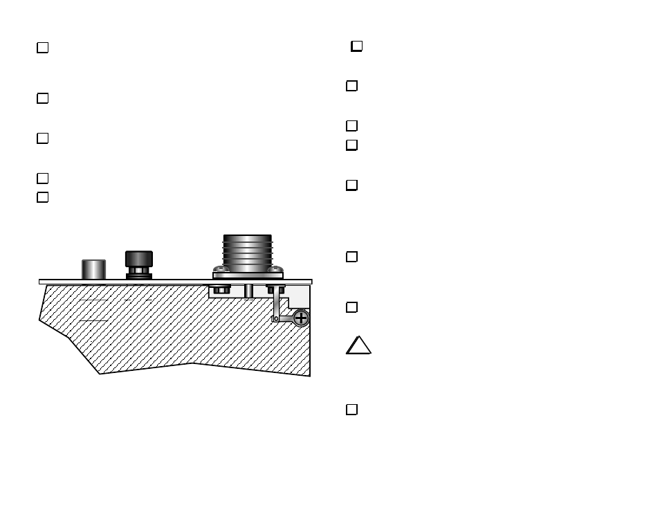
The two solder lugs will be used to form a ground strap between the
shield and rear panel as shown in Figure 3. Attach one lug to the shield
screw nearest the SO239 connector. The lug replaces the lock washer,
which can be saved as a spare.
Attach the second lug to the upper-right of the four screws holding the
SO239 connector to the rear panel. This lug also replaces the original lock
washer.
Using long-nose pliers, fold the second lug down at a 90-degree angle
so that it overlays the first as shown below. Trim the excess length off the
end of the first lug.
Solder the two lugs together.
Tighten the hardware to ensure good contact at both ends of the
ground strap.
J7
J2
E1
Figure 3
Turn the KPA100 assembly over carefully and install it in the K2, re-
connecting all cables. Make sure the left and right spring clips are touching
the side panels, and that none of the interconnecting cables are pinched.
Secure the KPA100 to the K2 only at the four locations identified as 1,
2, 5, and 6 in Figure 8 of your KPA100 manual (page 20). Use 4-40 x 3/16"
black pan head screws. Do not install the remaining two screws yet.
Remove the right side panel of the K2 (four screws).
Examine the cables connecting the K2 and KPA100. Move the ribbon
cable and speaker cable toward the front of the K2. They should not be
touching the KSB2 or KNB2 modules, if present.
Hold the right side panel up to the K2, and note where the KPA100
shield clip contacts the panel. Mark this spot with a pencil. Note: Be sure to
mark the inside of the panel. When you're looking for the spring clip
contact point, four of the five side panel screw holes should line up with
2-D fasteners. The fifth screw hole, at the top-middle of the side panel,
should line up with the grooved channel on the KPA100 heat sink.
Lay the side panel on a soft cloth. Using sand paper or a Dremel tool
(or equivalent), remove enough paint from around the marked location so
that the spring clip will make good contact. Paint should be removed from
an area about 1/4 to 1/2" (6-12 mm) in diameter.
Remove the left side panel. Mark the shield clip contact point, then
remove the paint from this area as described above.
i
The side panel screws that attach to the KPA100's heat sink thread
into the thin grooved channels. In the next step, be careful not to
overtighten these screws, as this could strip the grooves. If these grooves
ever do become stripped, you can replace the original 4-40 screws with 5-
40 Tap-Tite screws (Elecraft order #SDSCRKT.)
Attach the side panels to the K2 (five screws each). Observe the
caution above when securing side panel screws to the heat sink.
This completes the KPA100 shield upgrade.