Elecraft K2 Keying Modification Instructions User Manual
Page 4
4
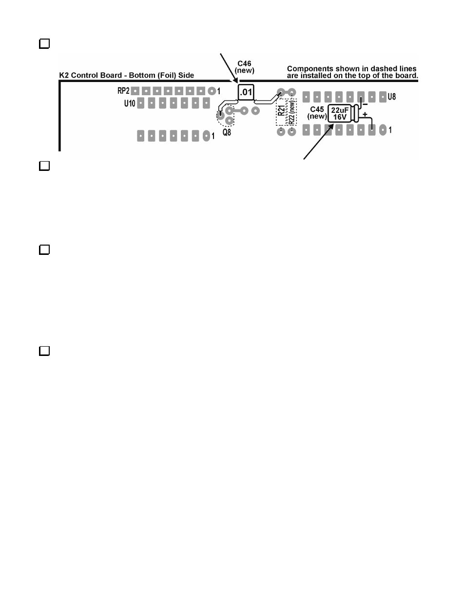
On the bottom (foil) side of the Control Board, Install the .01 µF ("103") capacitor (C46) from Q8-
base to the junction of D3 & R21.
On the bottom side of the Control Board, install a 22 µF 16VDC electrolytic capacitor (C45) from
U8 pin 2 (+ lead) to U8 pin 14 (- lead).
This completes all changes required to the K2 Control Board
Changes required to the bottom side of the K2 RF Board.
Remove the K2's bottom cover. Locate D36 which is on the bottom side of the RF board, 2-3/4"
(7cm) in from the left edge and 2" (5cm) up from the bottom edge of the PC board.
Note: In the following step, due to the density of components on the top side of the RF board, you
may find it difficult to clip the leads of the new D36 which will be installed from the bottom
side of the board in the following step. You may find it easier to pre-trim the diode leads so
they are flush with the top side of the RF board when the diode is installed before you
actually install the diode.
Replace D36 with a 5082-3081 PIN diode. Observe the proper polarity when installing this diode
(cathode band faces to the right as indicated by the component outline).
This completes the K2 Keying Modification.