Offset jack screw assembly, Butt hinge appl, Push/pull assembly – EFCO T300 Series User Manual
Page 9: Page 8
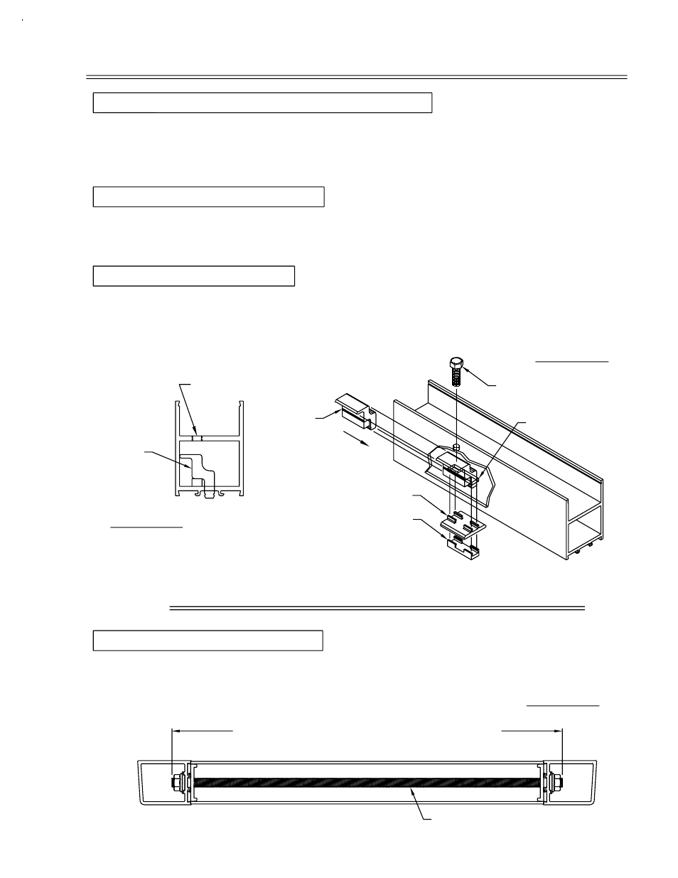
FIGURE #3
SECTION V: TIE ROD CUT LENGTH
STEP #4 TIE ROD CUT LENGTH
FIGURE #1
STEP #3 JACK SCREW CAPS
STEP #2 JACK SCREW INSERTION
FIGURE #2
STEP #1 OFFSET JACK SCREW BLOCK INSERTION
SECTION IV: OFFSET JACK SCREW ASSEMBLY
PAGE 8
SLOT IN TOP RAIL
CUT LENGTH = D.O.W. minus 2 3/4" T200
CUT LENGTH = D.O.W. minus 5 1/2" T300
#M120 OR #M151
Measure the tie rod (#M120 or #M151) as shown in Figure #3 and cut, if required, to the
formulas below.
Determine which door glazing is used. For 1/4" glass, use the 1/4" jack screw cap
(#HB18). For 1" glass, use the 1" jack screw cap (#HB19). Snap the correct jack screw
cap to the jack screw block. Use one cap per top rail. See Figure #2 below.
Insert one (1) jack screw (#IHP2/M103) per top rail. Tighten the screw enough to allow
the jack screw cap (#HB18 or #HB19) to be snapped to the jack screw block
(#K421/K432). See Figure #2.
Insert the offset jack screw block assembly (#K421/K432) through the end of the top rail
and down into the slot cut in the glazing side of the rail. Position the edge of the jack
screw assembly toward the side of the top rail with the hole prep for the jack screw.
See Figure #1.
ALIGN THIS EDGE
WITH HOLE PREP
#HB18 AT 1/4" GLASS
#HB19 AT 1" GLASS
#K421
#K432
OFFSET HOLE PREP
DPS/BB JULY 2000
#IHP2
#M103