Push pull assembly, Page 11 – EFCO T300 Series User Manual
Page 12
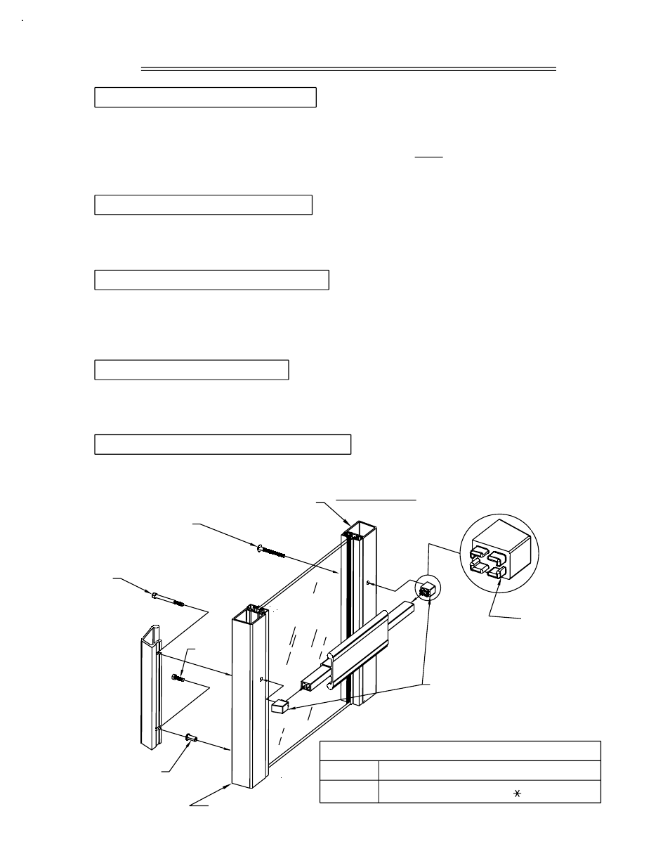
(DOOR OPENING WIDTH) (1/2) - 3.438"
PAIRS
SINGLES
STEP #14 PULL HANDLE APPLICATION
FIGURE #10
STEP #11 PULL HANDLE BOLTS
STEP #13 LOCK STILE BOLT
STEP #12 PUSH BAR APPLICATION
(DOOR OPENING WIDTH) - 3.500"
PUSH BAR CUT LENGTH FORMULA
SECTION VIII: PUSH/PULL ASSEMBLY
STEP #10 PUSH BAR END CAPS
PAGE 11
#M105
1/4"-20 X 2 1/2
HX-MS 18-8
Continue holding the push bar to the door and align the hole on the hinge stile with the
hole in the mounting cap. Attach the hinge stile of the push bar with the 1/4"-20 x 2 1/4"
PL-TH-MS (M104) dress bolt shown in Figure #10.
DPS/BB JULY 2000
TWO PART EPOXY
APPLIED TO LEGS
OF END CAPS
#I107 1/4"-20
RIV NUT
LOCK STILE
Slide the pull handle under the hex head bolts at the lock stile and tighten.
#IHP2
#M104
1/4"-20 X 2 1/4
PL-TH-MS 18-8
Hinge/Pivot Stile
HB20/HB21 PUSH
BAR END CAPS
Hold the push bar to the door and start the hex head bolt (#M105) at the lock stile as
shown in Figure #10. After installing the hex head bolts (#IHP2 and #M105), leave hex
head bolts loose, with a minimum 5/16" gap. This will allow the pull handle to slide under
the hex head bolt.
Start one (1) 1/4"-20 x 3/4" (#IHP2) hex head bolt into the factory installed riv nut located
in the lock stile. Insert one (1) 1/4"-20 x 2 1/2" (#M105) hex head bolt into the predrilled
hole in the lock stile.
If required, cut the push bar to length. The push bar must be cut from the hinge end.
Consult the chart below for the correct cut length formula. Insert the push bar end caps
into the ends of the push bar as shown in Figure #10. Note: To ensure a tight fit, EFCO
recommends applying a thin coat of two part epoxy to the legs of the end caps prior to
being inserted into the push bar. See Figure #10.