Tie rod assembly, Header preparatio, Closer adjustm – EFCO T300 Series User Manual
Page 10: Page 9, Figure #5, Figure #4, Figure #6, Figure #7
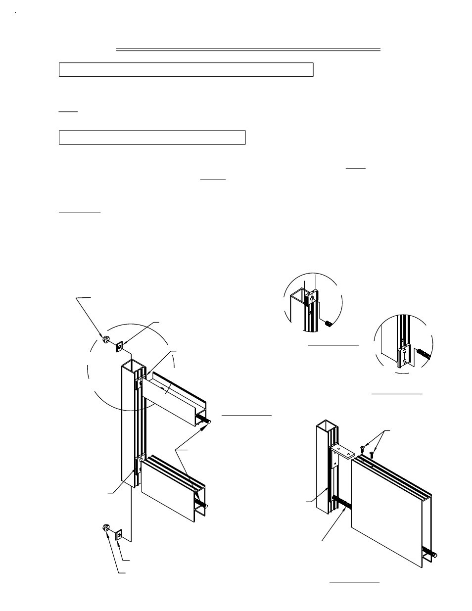
FIGURE #5
3/8"-16 HEX
LOCK NUT-ZC
#IQT1
#FS75
FIGURE #4
3/8"-16 ALL THREAD-ZC
#M120/#M151
FIGURE #6
SECTION VI: TIE ROD ASSEMBLY
STEP #5 TOP AND BOTTOM RAIL ADAPTOR INSERTION
STEP #6 TIE ROD AND RAIL ASSEMBLY
FIGURE #7
PAGE 9
#FS75
(T200 BEVELED STILE ONLY)
FS77
-
FOR T200
4" BOTTOM RAIL (8601)
FT03
-
FOR T200/T300
7 1/2" BOTTOM RAIL (8608)
#IQT1 (2)
3/8"-16 HEX
LOCK NUT-ZC
#M120/#M151
3/8"-16 ALL THREAD-ZC
K459 -
FOR T200/T300
10" BOTTOM RAIL (8561)
FS76 -
FOR T200 2 3/8" TOP RAIL (8600)
FT13 -
FOR T300 3 1/2" BOTTOM RAIL (8596)
#S123
12-24 X 3/4"
DPS/BB NOVEMBER 2000
Insert the tie rod (#M120 or #M150) through the adaptor and door stile. Apply two (2)
washers (#FS75) and two (2) (#IQT1) lock nuts per rail to the tie rod. Note: The washer is
required at the beveled stile T200 ONLY. Align the top and bottom rails over the tie rods
and rail adaptors and install the lock nuts and washers to the opposing stile, as shown in
Figure #6. Use a 9/16" combination wrench and tighten the lock nuts at each corner.
CAUTION: Over tightening the lock nuts may cause the door rails to bow.
Note: Follow the instructions above for 10" bottom rail assembly, and fasten the 10" bottom
rail to the K459 10" bottom rail adaptor clip with the supplied S123 #12-24 x 3/4" fasteners
(Figure 7). Attachment of the 10" bottom rail is through the top of the rail in prefabricated
countersink holes that provide the correct location for the S123 fasteners.
Slide the top rail adaptors (#FS76) into the vertical stiles and center the hole in the
adaptors over the top hole in the door stiles, as shown in Figure #4.
Note: Position the bottom rail adaptors by aligning the bottom hole of the adaptor with the
hole in the bottom of the stile, as shown in figure #5.