Dead load anchor, Wind load anchor – EFCO 5800 Series User Manual
Page 6
9/2000
PAGE 4
be filled in as additional mullions are erected.
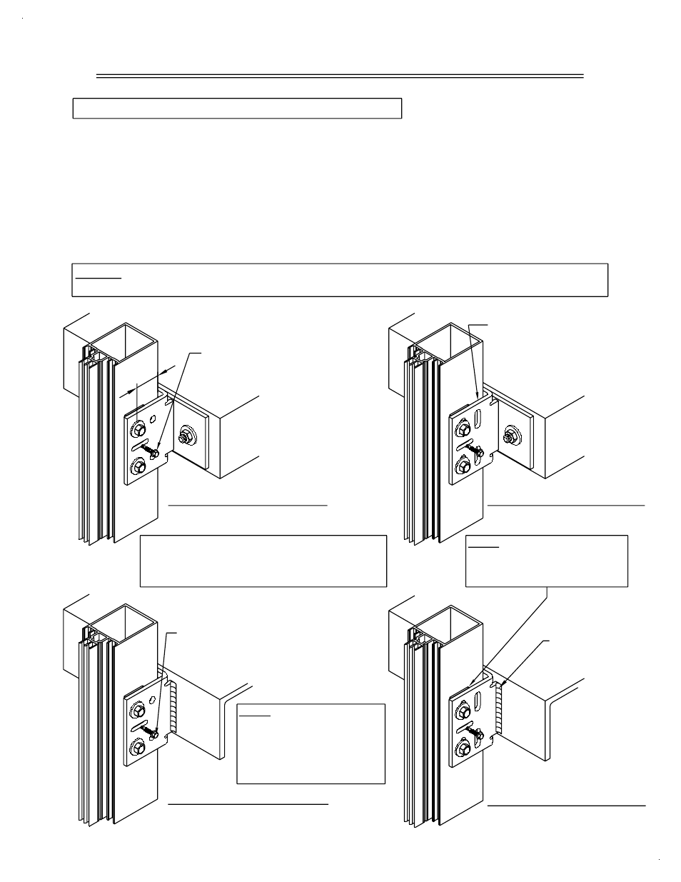
DEAD LOAD ANCHOR
BOLTED TO STRUCTURE
AFTER ANCHORING).
TEMPORARY ALIGNMENT
NOTE: On long runs, check overall frame dimensions at every fifth opening
to avoid dimensional build-up.
SCREW (REMOVE
WELDED TO STRUCTURE
DEAD LOAD ANCHOR
A MINIMUM OF 1" FROM THE
DRILL THROUGH THE MULLION AT
THE HOLE LOCATION IN THE CLIP
BACK OF THE MULLION.
COMPLETE THE BOLT CONNECTION
PER PROJECT SHOP DRAWINGS.
THE FLOOR SLABS MUST BE WITHIN THE
ADJUSTMENT CAPABILITY OF THE ANCHORING
SYSTEM. REFER TO THE PROJECT SHOP
DRAWINGS FOR THE ALLOWABLE ADJUSTMENT.
NOTE: REFER TO PROJECT
WELDING INSTRUCTIONS.
SHOP DRAWINGS FOR
PROTECT THE INSTALLED
GLASS AND METAL FROM
WELD SPLATTER.
WIND LOAD ANCHOR
WELDED TO STRUCTURE
MULLIONS.
NOTE: USE 1/16" HORSE-
SHOE SHIMS BETWEEN
THE STEEL ANCHORS AND
THE ANCHOR.
BOTH SIDES OF
FILLET WELD AT
WIND LOAD ANCHOR
BOLTED TO STRUCTURE
PERMANENTLY ATTACH
POSITION THE MULLION
STRUCTURE PER PROJECT
THE ANCHOR TO THE
SHOP DRAWINGS.
PLUMB AND TRUE.
Attach the midspan floor anchors to the mullions with temporary alignment
screws. Set the vertical mullion in place, plumb and true. Make permanent
attachment of base anchors, head anchors, and midspan floor anchors to
advance of erecting the horizontal members if desired, or the horizontals can
the building structure as specified in the approved project shop drawings.
After completing permanent anchorage, remove all temporary alignment
screws and fasteners. Multiple runs of vertical mullions can be set in
STEP #2 APPLY MIDSPAN FLOOR ANCHORS
SECTION II: VERTICAL FRAME INSTALLATION
1"
MIN.