Dynojet 250i: Control Panel Interface Upgrade (S/N 202xxxx) User Manual
Page 5
3
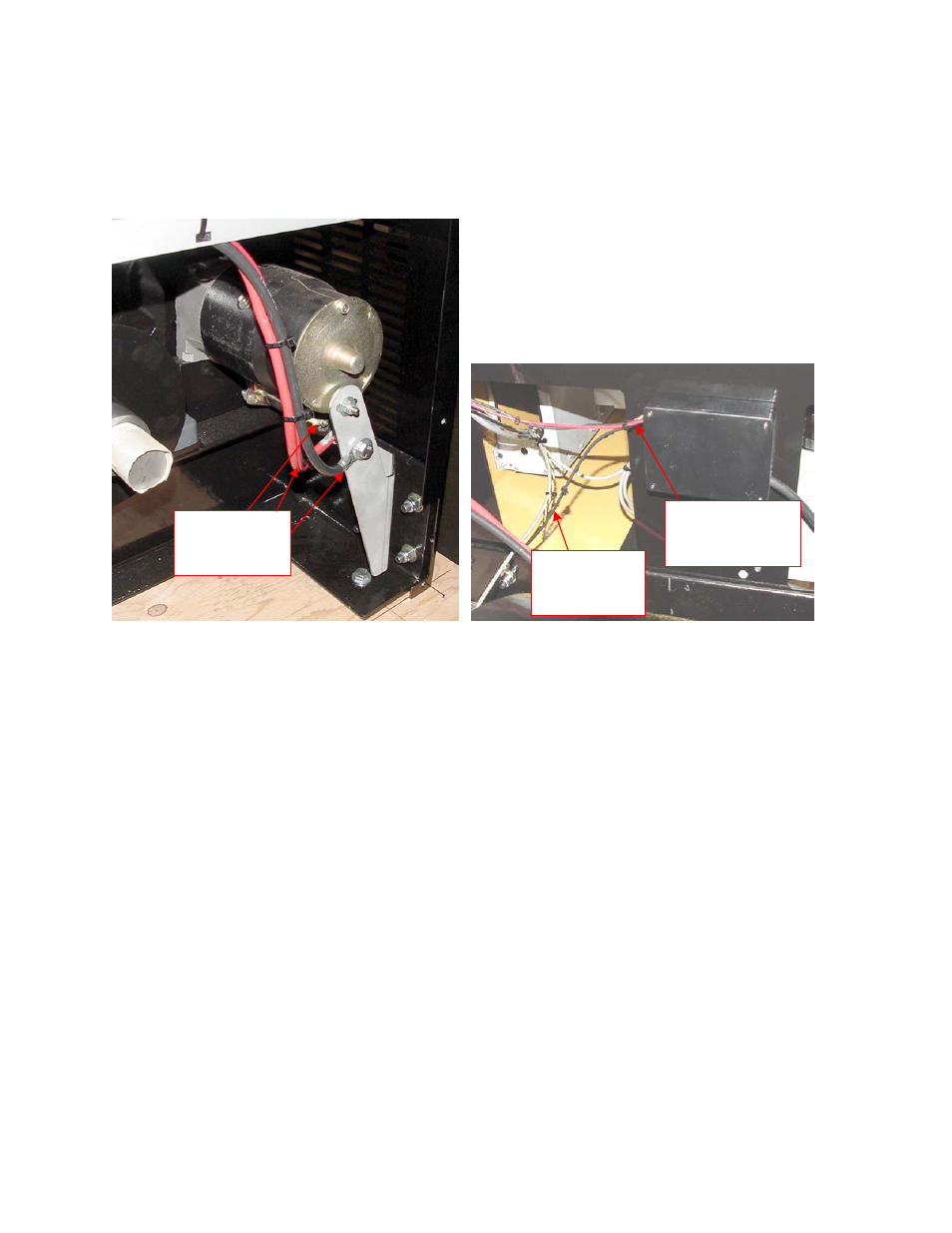
5. Disconnect the red battery cable from the starter and the black battery cable from the ground
connection. If your dyno does not have a starter brace as shown, contact Dynojet. Disconnect the
starter solenoid wire. All wires should be removed from the starter. Disconnect the red and black
wires that go into the black box on the back wall of the drum module.
6. If the starter switch has been installed through one of the cable access holes, remove the cable
access plate and feed the starter switch back into the dyno and coil up in the front inside of the dyno.
This will not be used with the new hardware.
7. If your dyno has an air brake installed, trace the wires from the air brake solenoid to the black box.
Cut the black solenoid wires at the point where the wires are extended to connect to the black box. If
your dyno has an external switch attached to your dyno room door, disconnect it from the black box.
8. Remove the black box and the external starter switch.
Remove
these wires
Remove Red
and Black wires
at other end
Disconnect
Yellow/Black
twisted wire