Installing the wall receptacle – Dynojet 250ix: Pre-Installation Guide User Manual
Page 46
Pre-Installation Guide for Model 200i/250i, 200iP/250iP, 250iX, and 250iPX Motorcycle Dynamometers
A P P E N D I X B
Locations Using 50 Hz Power (Locations other than North America and Japan)
B-8
I
NSTALLING
THE
W
ALL
R
ECEPTACLE
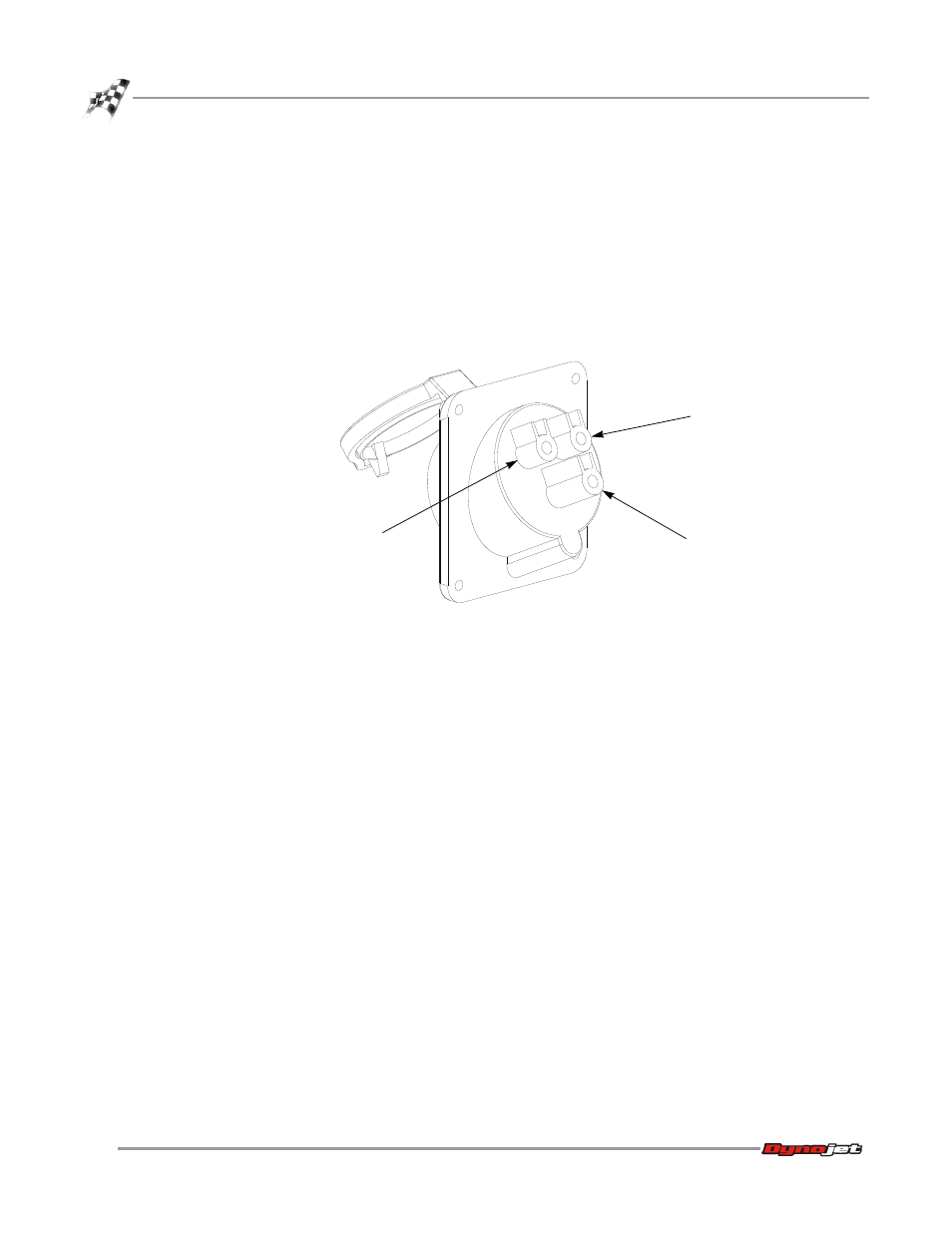
The wall receptacle is a single 240 volt 30A dedicated circuit with a ground.
The cable carrying the power to this receptacle should be 4.0 mm
2
(ten gauge) or
larger. Check with local building codes for the correct size.
1
Connect one of the 240V legs to the N terminal (white).
2
Connect the other 240V leg to the L terminal (no color).
3
Connect the ground conductor to the green terminal.
Figure B-2: Wire the Wall Receptacle
N terminal
(white)
L terminal
ground terminal
(green)
This manual is related to the following products: