Room layout-model 250ipx dyno, Px d – Dynojet 250ix: Pre-Installation Guide User Manual
Page 31
D Y N O P R E - I N S T A L L A T I O N I N F O R M A T I O N
Model 250iPX Dynamometer
Version 3
Pre-Installation Guide for Model 200i/250i, 200iP/250iP, 250iX, and 250iPX Motorcycle Dynamometers
23
R
OOM
L
AYOUT
—M
ODEL
250
I
PX D
YNO
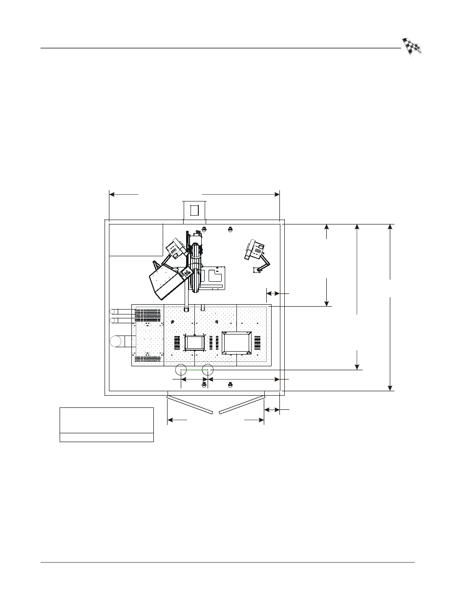
Use the following information to locate the necessary dyno equipment, power outlets,
compressed air, and properly set up your dyno room.
For more detailed information about the pit requirements, refer to the pit
specifications (P/N 98229104) you received from your salesman.
Note: The pit must be provided with exhaust ventilation at a rate of not less than
1CFM per ft.
2
of floor area (26CFM for the 250iP pit) taken from a point 300 mm
(12 in.) off the floor of the pit at all times that the building is occupied or when
vehicles are parked over this area.
Figure 15: Room Layout—Model 250iPX Top View
158.75 cm (62.50 in.)*
*Dimensions are given for reference only and will vary with room size.
60.96 cm (24.00 in.)
182.88 cm (72.00 in.)
365.76 cm (144.00 in.)*
40.64 cm (16.00 in.)*
30.48 cm
(12.00 in.)*
min. dimensions for
standard carriage
177.39 cm (69.84 in.)
extended carriage
220.98 cm (87.00 in.)
standard carriage
320.04 cm (126.00 in.)
extended carriage
365.76 cm (144.00 in.)
457.20 cm
(180.00 in.)*
provide compressed air for the:
•optional air brake
•optional AFR‐4 pump
provide an outlet for dyno power
KU071