Unpacking & pre-installation, Installation & mounting, Amplifier connections – Code 3 V-Con Siren User Manual
Page 4
4
Unpacking & Pre-installation
After unpacking your 3690 series siren, carefully inspect the unit and associated parts for any damage that may have been caused in
transit. Report any damage to the carrier immediately.
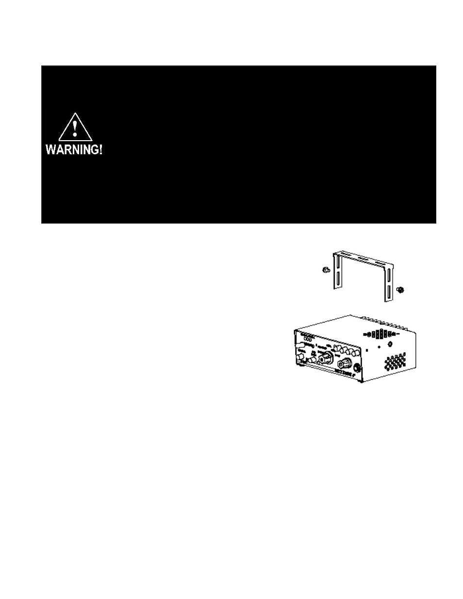
Installation & Mounting
The 3690 series siren may be mounted above the dash, below the dash, on a
tunnel or in a rack with the mounting bracket (bail) and the hardware supplied
(see Fig. 2). Ease of operation and convenience to the operator should be the
prime consideration when mounting the siren and controls.
Install the siren on the bail bracket using the 1/4-20 x 1/2" bolts and
1/4" flat washers supplied. Longer bolts will prevent removal of
the chassis from the cover and may damage internal compo-
nents. See Figure 2 for assembly and positioning details.
NOTE: Set-ups and adjustments will be made in subsequent steps,
depending upon the model and options purchased, that may require
access to the rear area of the unit. Plan the installation and wiring
accordingly.
Amplifier Connections
Siren Amplifier Connector - As a standard feature, the Siren and Auxiliary sections (L4 models) of your unit come
equipped with a screw terminal block. To terminate the wires, strip approximately 1/4" of insulation from the end of each
wire and insert it in the appropriate terminal. Tighten the screw and proceed to the next connection.
Figure 2
All devices should be mounted in accordance with the manufacturer's instructions and securely fastened to vehicle
elements of sufficient strength to withstand the forces applied to the device. Ease of operation and convenience to the
operator should be the prime consideration when mounting the siren and controls. Adjust the mounting angle to allow
maximum operator visibility. Do not mount the Hand-Held Controller in a location that will obstruct the drivers view.
Mount the Hand-Held Controller mounting base in a convenient location to allow the operator easy access. Devices
should be mounted only in locations that conform to their SAE identification code as described in SAE Standard
J1849. For example, electronics designed for interior mounting should not be placed underhood, etc. Controls should
be placed within convenient reach* of the driver or if intended for two person operation the driver and/or passenger. In
some vehicles, multiple control switches and/or using methods such as “horn ring transfer” which utilizes the vehicle
horn switch to toggle between siren tones may be necessary for convenient operation from two positions.
*Convenient reach is defined as the ability of the operator of the siren system to manipulate the controls from hir
normal driving/riding position without excessive movement away from the seat back or loss of eye contact with the
roadway.