Assembly – Craftsman 987.799601 User Manual
Page 10
Attention! The text in this document has been recognized automatically. To view the original document, you can use the "Original mode".
ASSEMBLY
ASSEMBLY FOR WALK-BEHIND VACUUMING OR USING THE CHIPPER
STEP
1: REMOVE
OR INSTALL SHREDDER SCREEN
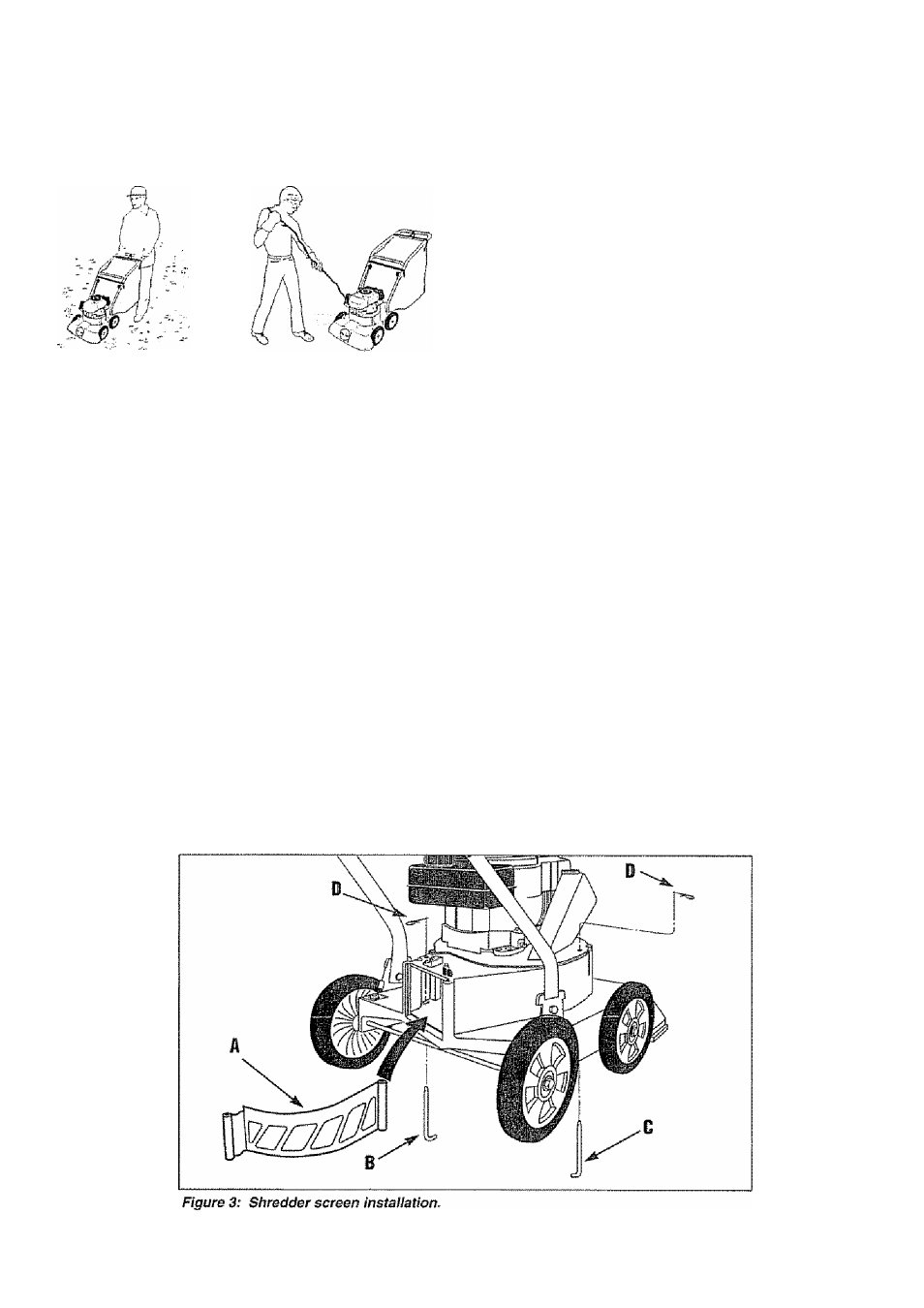
A shredder screen
(A,
Figure 3) is factory-installed
inside the processing chamber. Vacuumed or chipped
material passes through the slots in the screen before it
is discharged. The screen produces up to an 8:1
reduction of material.
The screen is designed for use only with dry materials.
Before processing damp materials, remove the screen to
reduce clogging and to improve air flow inside the
processing chamber. Before chipping a large number of
branches, remove the shredder screen for faster
discharge of the chips.
To Remove Shredder Screen:
1.
Stop the engine, disconnect the sparkplug wire
from the sparkplug, and make sure that ail moving
parts have come to a complete stop.
2.
To remove rear rod
(B,
Figure 3), remove the
collection bag or the blower deflector (if installed). Then,
remove the hair pin clip (D) and puli the rod out through
the bottom of the deck
3.
Use sturdy supports to prop up the right side of the
machine a few inches. Then, remove the hair pin clip
(D) and puli the front rod (C) out through the bottom of
the deck
4.
Pull the screen
(A)
out of the discharge opening. Re
install the rods and hair pin dips on the screen for safe
keeping.
IMPORTANT:
THE HAIR PIN CUPS SUPPLIED WITH
THE SCREEN ARE THE ONLY STYLE FASTENERS
THAT SHOULD BE USED. DO NOT USE
SUBSTITUTES OR FAILURE OF EQUIPMENT OR
PERSONAL INJURY COULD RESULT.
5.
Remove supports from beneath machine.
To install Shredder Screen:
1.
Stop the engine, disconnect the spark plug wire
from the spark plug, and make sure that ail moving
parts have come to a complete stop.
2.
Remove the collection bag Remove the rods and
hair pin clips which were stored on the shredder screen.
Insert the screen
(A)
into the processing chamber with
the flat, angled end facing to the rear and the curve in
the screen facing to the right See Figure 3. Align
mounting holes in screen with the holes in deck.
3. Using sturdy supports, prop up the right side of the
machine a few inches, insert front rod (C) up through
bottom of deck, into screen mounting hole, and out
through the top of the deck. Test that the rod is through
the screen by pulling on the screen - the screen should
not move Secure rod with hair pin clip (D).
4.
Insert rear rod
(B)
up through bottom of deck, into the
screen mounting hole, and out through the top of the
deck. Make sure that the rod is in the screen by trying to
move the screen from side to side. Secure the rod with
the hair pin dip (D)
5.
Re-install the collection bag-
10