Assembly – Craftsman 536.881800 User Manual
Page 8
Attention! The text in this document has been recognized automatically. To view the original document, you can use the "Original mode".
ASSEMBLY
TO ASSEMBLE THE HANDLE AND
CRANK ASSEMBLY
1. Cut tie holding shift rod to lower
handle and move shifter to the first
forward gear.
2. Cut and discard the plastic tie that
secures the crank assembly.
3. Loosen, but do not remove, the
screws, flatwashers, lockwashers,
and hex nuts in the upper holes of
the lower handle. See Figure 3.
4.
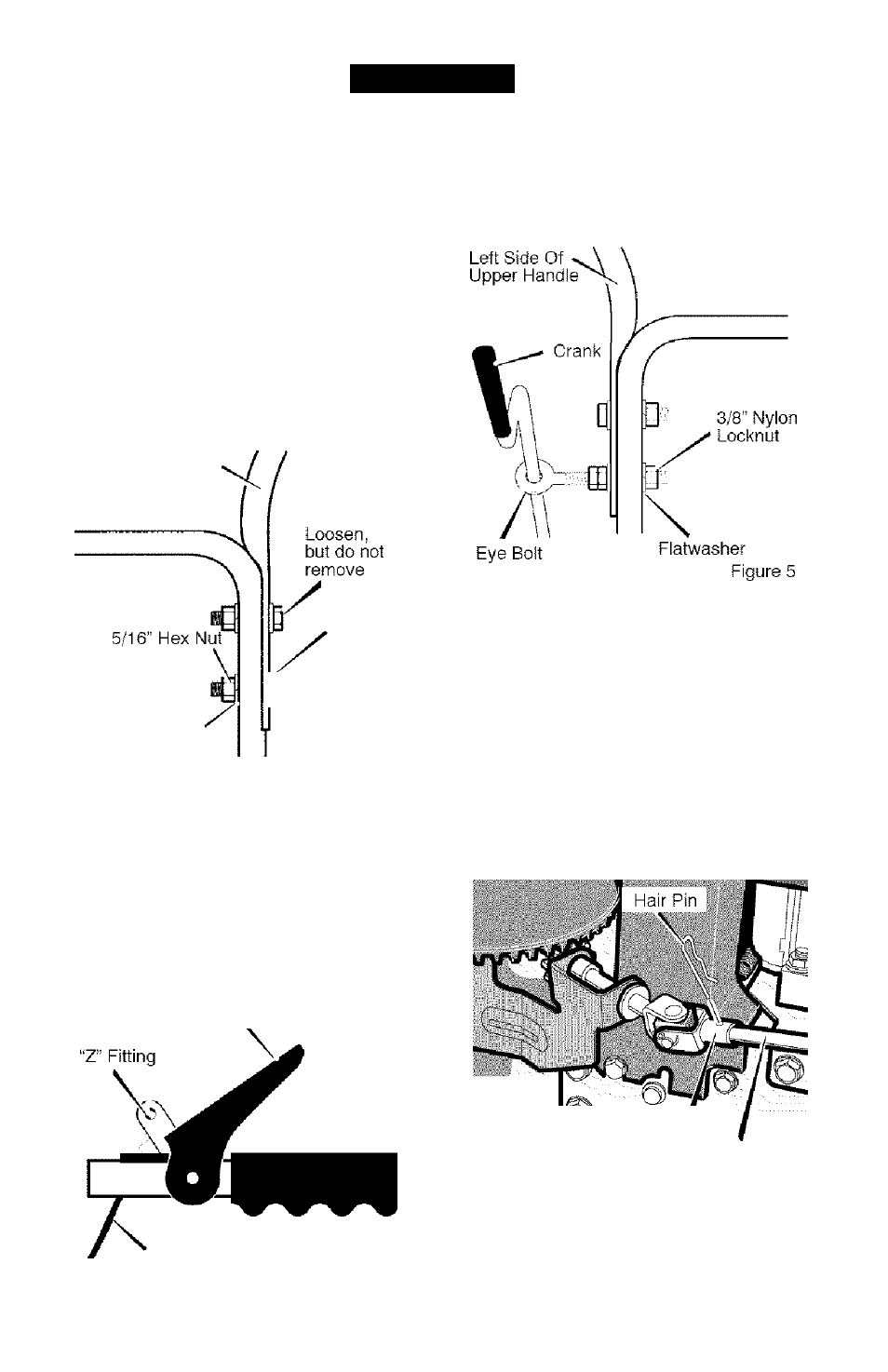
Remove the fasteners and the eye
bolt from the lower holes of the low
er handle See Figure 5.
Right Hand Side
Of Upper Handle
11/32"
Flatwasher
te /
6”
y / Screw
5/16” Split
Lockwasher
Figure 3
NOTE:
Make sure the cables are
not caught between the upper and
lower handle.
5. Raise the upper handle into operat
ing position.
NOTE:
If the cables have become dis
connected form the drive levers, rein
stall the cables as shown in Figure 4.
Lever
6.
Install the fasteners that were re
moved in step 4. DO NOT tighten
until all bolts are in place.
Attach the crank rod to the universa!
joint assembly with the hair pin. See
Figure 6.
Tighten nut on
eye bolt.
Make sure
eye bolt
is properly aligned and the
crank
can freely rotate.
Tighten all handle and panel bolts.
Universal Joint Assernbly
Crank'Rod
Figure 6
Control Cable
Figure 4
F-0410108L