Cisco 3545 MCU User Manual
Page 20
2-14
Installation and Upgrade Guide for Cisco Unified Videoconferencing 3545 MCU Releases 5.6 adn 5.7
OL-17013-01
Chapter 2 Installing the Cisco Unified Videoconferencing 3545 MCU
Mounting the Cisco Unified Videoconferencing 3545 Chassis in a 19-inch Rack
Before You Begin
The requirements are as follows:
•
Cisco Unified Videoconferencing 3545 chassis
•
Proper clearance at the sides of the unit to allow adequate ventilation, and at least 20 cm clearance
at the back of the chassis to allow access to the boards and cable connections
•
Available IP network ports on the switch for the MCU and EMP
•
A grounded AC power outlet
•
A 10BaseT or 100BaseT LAN cable
•
Ambient room temperature range of 32
o
to 122
o
F (0
o
to 50
o
C)
•
Non-condensing relative humidity range of 5% to 85%
Procedure
Step 1
Disconnect all cables including the power cables.
Step 2
Place the Cisco Unified Videoconferencing 3545 chassis right-side up on a hard flat surface, with the
front panel facing you.
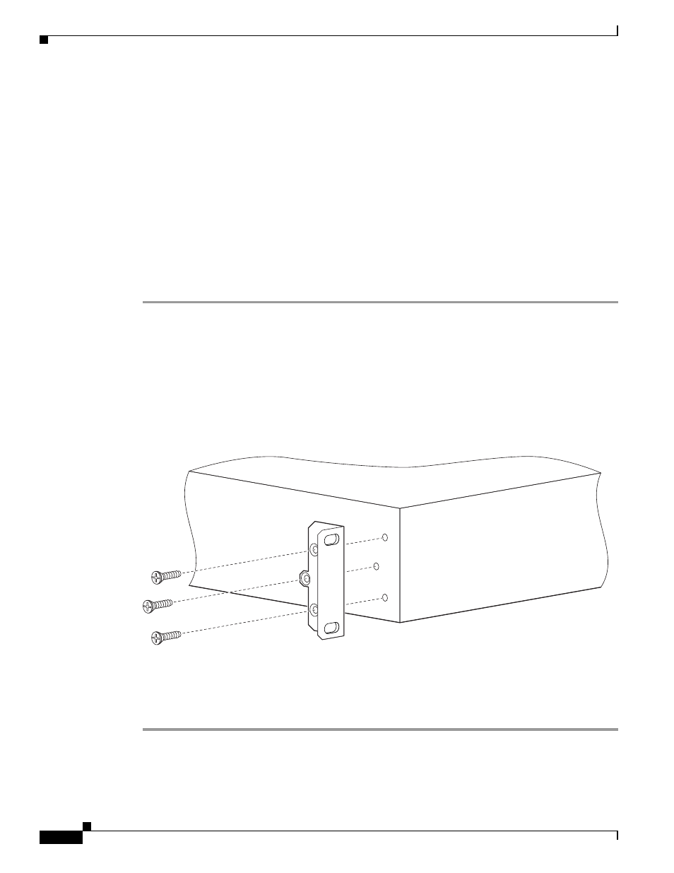
Step 3
Position a mounting bracket over the mounting holes on each side of the Cisco Unified
Videoconferencing 3545 chassis, as shown in
Figure 2-3
.
Step 4
Pass the screws through the brackets and tighten them into the screw holes on each side of the
Cisco Unified Videoconferencing 3545 chassis using a suitable screwdriver.
Figure 2-3
Fitting a Bracket for Rack Mounting
Step 5
Insert the Cisco Unified Videoconferencing 3545 chassis into the 19-inch rack.
Step 6
Fasten the brackets to the side rails of the rack.
Step 7
Make sure that the air vents at the sides of the Cisco Unified Videoconferencing 3545 chassis are not
blocked.
157267