Cisco 3545 MCU User Manual
Page 18
2-12
Installation and Upgrade Guide for Cisco Unified Videoconferencing 3545 MCU Releases 5.6 adn 5.7
OL-17013-01
Chapter 2 Installing the Cisco Unified Videoconferencing 3545 MCU
Physical Description
Physical Description of the Cisco Unified Videoconferencing 3545 MCU
Module
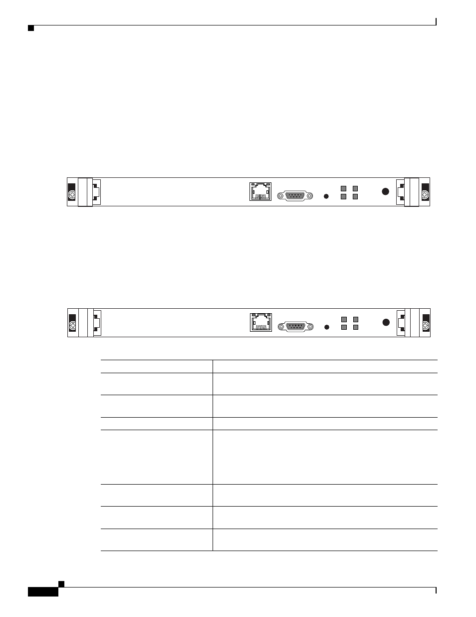
The Cisco Unified Videoconferencing 3545 MCU module has a 10/100BaseT Ethernet port on the front
panel that uses an RJ-45 connector to connect to the network. There is an asynchronous, 9-pin serial port
that you can use with a hyperterminal program to configure and monitor the module.
shows the front panel of the Cisco Unified Videoconferencing 3545 MCU module.
Table 2-1
describes the components of the front panel.
Figure 2-1
Cisco Unified Videoconferencing 3545 MCU Front Panel
Physical Description of the Cisco Unified Videoconferencing 3545 EMP
Module
shows the front panel of the Cisco Unified Videoconferencing 3545 EMP board.
Table 2-1
describes the components of the front panel.
Figure 2-2
Cisco Unified Videoconferencing 3545 EMP Front Panel
157270
10/100Base T-1
SERIAL
RST
ACT
ALARM
CPU-Hight
GK Reg
SWAP
RDY
Table 2-1
Front Panel Components
Component
Description
10/100 BaseT-1 connector
An RJ-45 connector that provides the primary Ethernet connection
for the IP network port.
SERIAL connector
A DB-9 connector that allows you to connect a PC terminal for local
configuration.
RST button
Allows you to reset the board manually.
GK Reg LED (on the
Cisco Unified
Videoconferencing 3545 MCU)
MC LED (on the Cisco Unified
Videoconferencing 3545 EMP)
Lights green when the Cisco Unified
Videoconferencing 3545 MCU is registered with a gatekeeper, or
when there is no gatekeeper registered and the auto attendant feature
is enabled.
Lights green when the EMP is registered with the MCU.
CPU High LED
Lights green when more than 50% of the MCU/EMP resources are
in use.
ACT LED
Lights green to indicate that there is at least one currently active
conference on the MCU/EMP.
ALARM LED
Lights green to indicate that an error has occurred and the
MCU/EMP requires resetting.
157271
10/100Base T
SERIAL
RST
ACT
ALARM
CPU-Hight
MC
SWAP
RDY