Active woofer, Q' if you have an additional front speaker system, Q' if your tv monitor uses separate speakers – Sony STR-D965 User Manual
Page 7: Selecting the impedance (str-d965 only), Selecting the speaker system, Tvafcr hookups, Overview, Hookups, Getting started, Where do / go next
Attention! The text in this document has been recognized automatically. To view the original document, you can use the "Original mode".
Getting Started
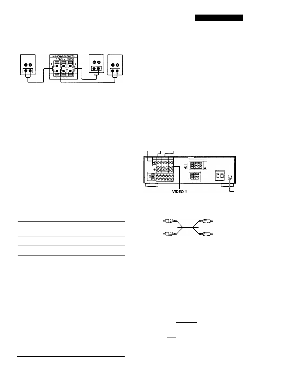
Rear and center speakers
Rear speaker
(R)
Receiver
Rear speaker
Center speaker (L)
Where do / go next?
To complete your system, go to "AC Hookups" on page 8. If
you want to connect video components to enjoy surround
sound when watching TV programs or video tapes, go on to
the next section.
Active woofer
Receiver
Active woofer
'Q' If you have an additional front speaker system
Connect them to the FRONT SPEAKERS B terminals.
'Q' If your TV monitor uses separate speakers
You can connect one of them to the SURROUND
SPEAKER CENTER terminals for use with Dolby Pro
Logic Surround Sound (see page 17).
Selecting the impedance (STR-D965 only)
Set the IMPEDANCE SELECTOR for the front speakers
as indicated in the table below. Check the instruction
manual of your speakers if you're not sure of the
impedance. (This information is usually printed on a
label on the back of the spaeaker.)
if nominal impedance of Set IMPEADANCE SELECTOR to
your speaker is
4 ohms or higher
40
8 ohms or higher
80
Selecting the speaker system
If you connect only one set of front speakers, set the
SPEAKERS selector on the front panel to A. If you
connect two sets of front speakers, see the following:
To drive
Set SPEAKERS selector to
Speaker system A (connected
to the FRONT SPEAKERS A
terminals)
A
Speaker system B (connected
to the FRONT SPEAKERS B
B
terminals)
Both speaker systems A and B
(parallel connection)
A+B*
■'Do not use A+B with SURROUND ON.
TVAfCR Hookups
Overview
This section describes how to connect video
components to the receiver. For specific locations of the
jacks, see the illustration below.
MONITOR TV VIDEO 2
What cables will I need?
• Audio/video cable (not supplied) (1 for each TV or LD
player; 2 for each VCR)
Yellow
White (L) =ClH!l“
Red(R)
Yellow
«mlg3= White (L)
Red (R)
• Video cable (not supplied) (1 for a TV)
Yellow -riLlSlI”™------------ mnii(g3= Yellow
Hookups
The arrow indicates signal flow.
TV
Receiver
TV
TV
r-®
(continued)