Cdp-338esd/608esd, Section 3 diagrams, 1. circuit boards location – Sony cdp 338esd User Manual
Page 5: Power board, V *v
Attention! The text in this document has been recognized automatically. To view the original document, you can use the "Original mode".
CDP-338ESD/608ESD
SECTION 3
DIAGRAMS
REFERENCE
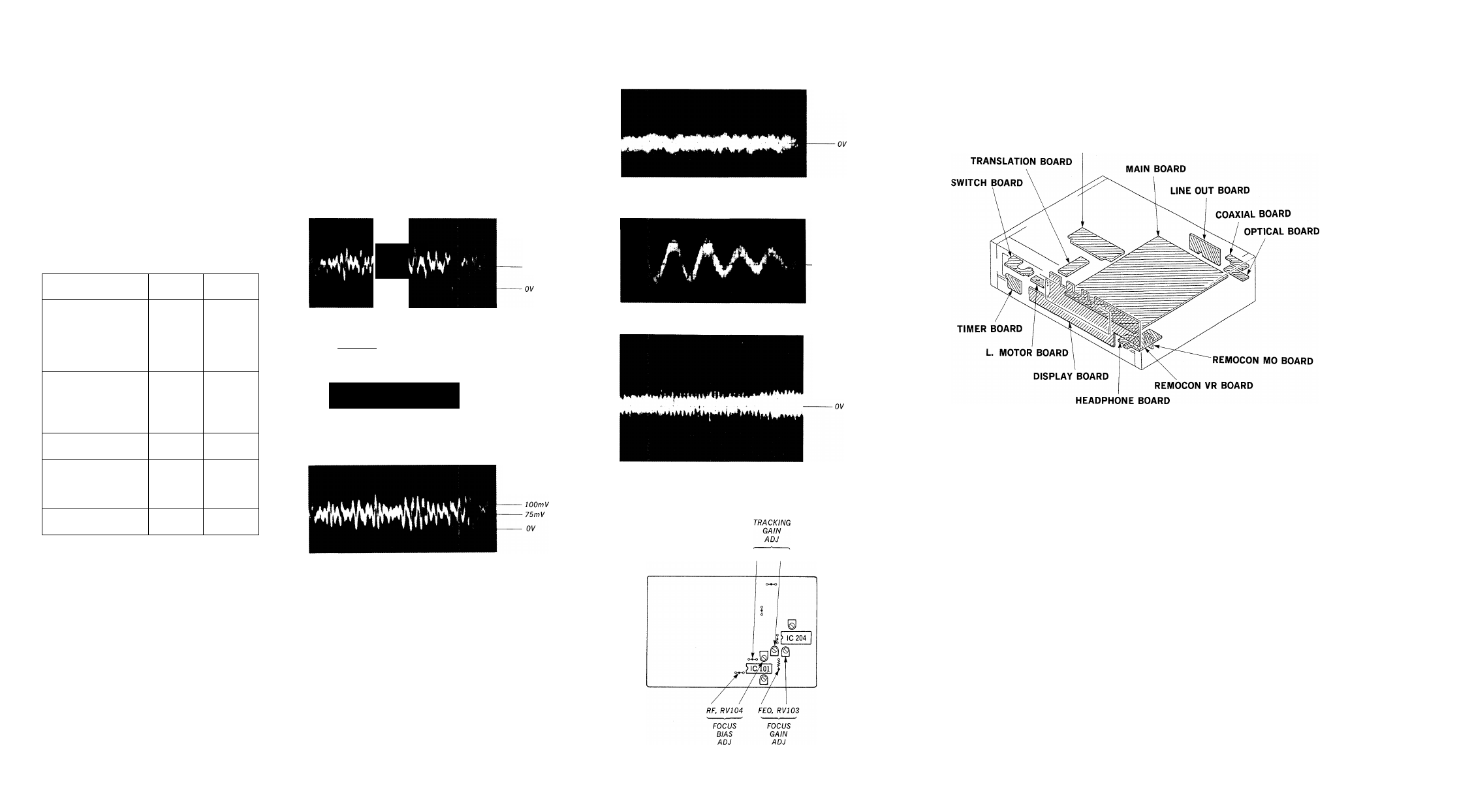
Focus/Tracking Gain Adjustments
A frequency responce analyzer is necessary in order to perform
this adjustment exactly.
However, this gain has a margin, so even if it is slightly off,
there is no problem. Therefore, do not perform this adjustment.
Focus/tracking gain determines the pick-up follow up (vertical
and horizontal) relative to mechanical noise and shock when the
2-axis device operate.
However, as these reciprocate, the adjustment is at the point
where both are satisfied.
• When gain is raised, the noise when the 2-axis device operates
increases.
• When gain is lowered, mechanical shock and skipping occurs
more easily.
• When gain adjustment is off, the symptoms below appear.
Gain
Symptoms
Focus
Tracking
• The time until music
starts becomes longer
for ■ ^ O or automatic
selection. (Kl
tons pressed.) (Normally
tapes about 1 seconds.)
low
low or high
• Music does not start and
disc continues to rotate
for ■ -> > or automatic
selection.
(KKl, OCH buttons pressed.)
-
low
• Disc table opens shortly
after ■->•[>.
low or high
-
• Sound is interrupted
during PLAY or time
counter display stops
progressing.
—
low
• More noise during 2-axis
device operation.
high
high
The following is a simple adjustment method.
—Primary Adjustment-
Note
: Since exact adjustment cannot be performed, remember
the positions of the controls before performing the adjust
ment. If the position after the primary adjustment are only
a little different, return the controls to the original posi
tion.
Procedure :
oscilloscope
(DC range)
main board
TP (FEO)
O
O
TP (TEO) o^- -
I
,
------------L
0 +
o-
1. Keep the set horizontal.
(
If the set is not horizontal, this adjustment
\
cannot be performed due to the gravity against the
2-axis device.
/
2. Insert disc (YEDS-18 : Fifth Selection) and press 0 button.
3. Connect oscilloscope to main board TP (FEO).
4. Adjust RV103 so that the waveform is as shown in the figure
below, (focus gain adjustment)
5. Connect oscilloscope to main board TP (TEO).
6. Adjust RV102 so that the waveform is as shown in the figure
below, (tracking gain adjustment)
VOLT/DIV:
IV
TIME/DIV: 2mS
3-1. CIRCUIT BOARDS LOCATION
POWER BOARD
Incorrect Examples (fundamental wave appears)
low tracking gain
WA
VOLT/DIV:
lOOmV
TIME/DIV: 2ms
100 mV
VOLT/DIV:
IV
TIME/DIV: 2mS
-OV
' Incorrent Examples (DC level changes more than on adjusted
waveform)
_______
low focus gain
VOLT/DIV:
lOOmV
TIME/DIV: 2mS
high tracking gain
(higher fundamental wave than for low gain)
VOLT/DIV:
IV
TIME/DIV : 2mS
V *V '/
-250mV
high focus gain
OV
VOLT/DIV:
lOOmV
TIME/DIV: 2mS
Adjustment Location : main board
TEO, RV102