Identifying parts and controls – Sony GDM-400PS User Manual
Page 5
Attention! The text in this document has been recognized automatically. To view the original document, you can use the "Original mode".
Getting Started
Identifying Parts and Controls
See the pages in parentheses for further details.
GDM-500PS is used for illustration purposes throughout
this manual.
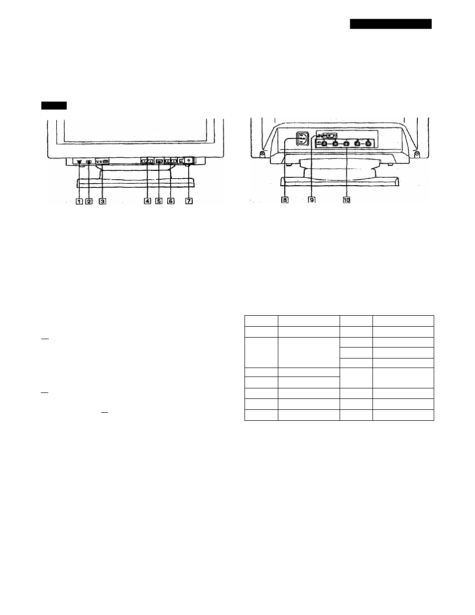
Front
[T]
RESET (reset) button (page 17)
Resets the adjustmente to the factory settings.
d] ASC (auto sizing and centering) button
(page 7)
Automatically adjusts the size and centering of the
images.
[3]
INPUT (input) button and H015/BNC
indicators (page 8)
Selects the HD15 or 5BNC video input signal. Each time
you prf^s this button^ the input signal and
corresponding indicator alternate.
ril
17)
Adjust the picture brightness.
Function as the (4/'^) buttoi^s when adjusting other
items.
[si MENU (menu) button (pages 8 -17)
Displays the MENU OSD.
(U Q (contrast) (*'■/■» ) buttons (pages 8 - 1 7 ,
22
)
Adjust tlw contrast.
Function as the (♦“/"^►) buttons when adjusting other
items.
[7] Ci)
(power) switch and indicator (pages 19,
22
)
Turns the monitor on or off.
The inditator lights up in green when the monitor is
turned on, and lights up in orange when the monitor is
m power caving mode.
AC IN connector
Provides AC power to the monitor.
Video input 1 connector (HD 15)
Inputs RGB video signals (0.700 Vp-p, positive) and
SYNC signals.
©®<3)(D®
Pin No.
Signal
Pin No.
Signal
1
Red
8
Blue Ground
2
Green
(Composite
Sync on Green)
9
DDC + 5V*
10
Ground
11
ID (Ground)
3
Blue
12
Bi-Directional
Data (SDA)*
4
ID (Ground)
5
DDC Ground*
13
H. Sync
6
Red Ground
14
V. Sync
7
Green Ground
15
DataClock(SGL)*
DUplay Data Channel (DDC) Standard of VESA
^ Video input 2 connector (5 BNC)
Inputs RGB video signaJs (0.700 Vp-p, positive) and
SYNC signalsT