Note, Power saving function, Damper wires plug & play – Sony GDM-400PS User Manual
Page 19
Attention! The text in this document has been recognized automatically. To view the original document, you can use the "Original mode".
Power Saving Function
This monitor meets the power-saving guidelines set by
VESA and Energy Star, as well as the more stringent
NUTEK.
If the monitor is connected to a computer or video graphics
board that is VESA DPMS (Display Power Management
Signaling) compliant, the monitor will automatically reduce
power consumption in three stages as shown below.
You can set the delay time before die monitor enters the
power saving mode using the OSD. Set dre time according
to "Setting the power saving delay time" on page 16.
Note
If no video signal is input to the monitor, the "NO INPUT
SIGNAL" message (page 20) appears. After the delay time has
passed, the power saving function autcnnatlcaUy puts the morvitor
into the active-off mode and the Ò indicator lights up orange. Once
the horizontal and vertical sync signals are detected, the monitor
automatically resumes its normal operation mode.
Power consumption
mode
Screen
Horizontal
sync signal
Vertical
sync signal
Power consumption
Recovery time
d) indicator
1
Normal op>eration
actíve
present
present
S160W (GDM-500PS)
S130 W (GDM-400PS)
Green
2
Standby (1st mode)
blank
absent
present
S 100 W (CDM-500PS)
S85W(GDM-400PS)
Approx. 3 sec.
Green and orange
alternate
3
Suspend (2nd mode)
blank
present
absent
S15W
Approx. 3 sec.
Green and orange
alternate
4
Active-off (3rd mode)
blank
absent
absent
S5W
Approx. 10 sec.
Orange
5
Power-off
—
—
—
OW
—
Off
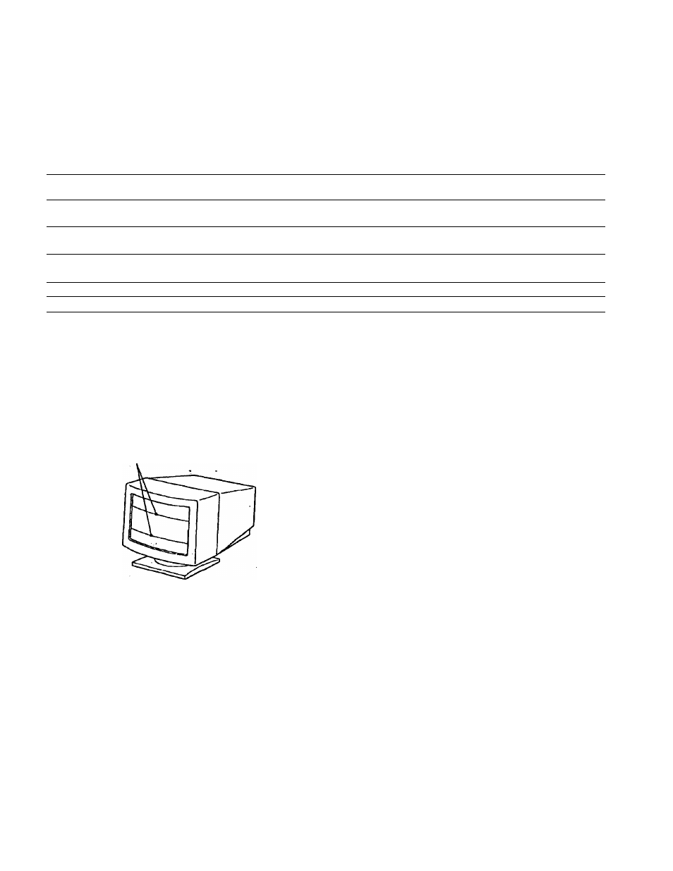
Damper Wires
Plug & Play
When viewing a white background, very thin horizontal
tines may be visible on the screen as shown below. These
lines are the shadows of the damper wires and are
characteristic of CRTs that use aperture grilles. The wires
are attached to the aperture grille on the inside of the
Trinitron tube and prevent the vibration of the aperture
grille.
Damper wires
This monitor complies with the DDC"*1, DDC2B, DDC2AB
and DDC2B+ Display Data Channel (DDC) standards of
VESA.
When a DDCl host system is connected, the monitor
synchronizes with the V. CLK in accordance with the VESA
standards and outputs the EDID (Extended Display
Identification Data) to the data line.
When a DDC2B, DDC2AB or DDC2B+ host system is
connected, the monitor automatically switches to the
appropriate standard.
DDC"* is a trademark of the Video Electronics Standard
Association.
Note
When using Windows* 95, the DDC standard docs not apply to ihe
5 BNC connectors. If you use the DDC standard, connect the HD15
connector to the computer with the supplied video signal cable.
19