Carrier 30HL050 User Manual
Page 8
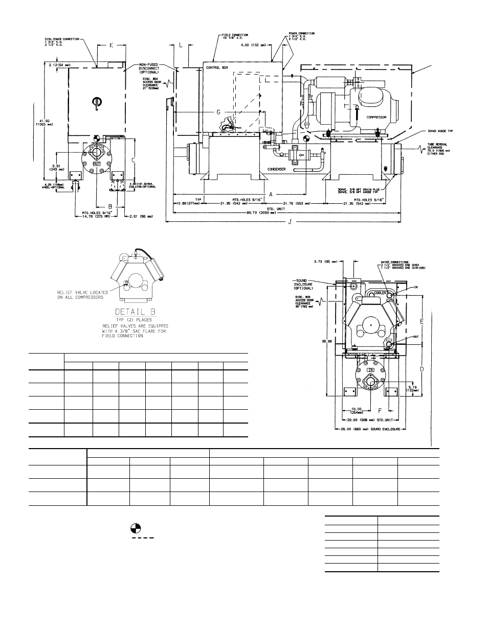
UNIT
30HWC,S
DIMENSIONS — in. (mm)
A
B
C
D
E
F
G
018
47.50
(1206)
9.90
(251)
14.00
(356)
18.15
(461)
17.95
(456)
6.69
(170)
34.20
(869)
025
48.30
(1227)
9.90
(251)
15.50
(394)
18.15
(461)
17.95
(456)
6.69
(170)
34.20
(869)
028
48.00
(1219)
10.00
(254)
15.80
(401)
18.15
(461)
17.95
(456)
6.69
(170)
34.20
(869)
035
48.20
(1224)
10.00
(254)
15.90
(404)
18.15
(461)
17.95
(456)
6.69
(170)
34.20
(869)
040
47.80
(1214)
10.00
(254)
15.90
(404)
18.45
(469)
17.36
(441)
6.40
(163)
32.94
(837)
DISCONNECT
(Amps)
LOCATION — in. (mm)
MODEL 30HWC,S (See Table Below)
J
K
L
018---
025---
028---
035---
040---
80
77.61
(1971)
4.38
(111)
3.33
(85)
100,200,
600,800,900
100,200,
600,900
100,200,
600,900
100,200,
600,900
100
100
79.61
(2022)
5.00
(127)
4.33
(110)
500
500,800
500,800
800
200,
600,900
200
83.74
(2127)
10.00
(254)
7.46
(189)
—
—
—
500
500,800
LEGEND
D.
— Diameter
Disc.
— Disconnect
K.O.
— Knockout
SCH.40 — Schedule 40 Pipe
NOTES:
1.
Denotes center of gravity.
2.
Denotes accessory or factory-installed option.
3. Dimensions are in inches. Dimensions in ( ) are in millimeters.
MODEL
VOLT-Hz
100
575-60
200
380-60
500
208/230-60
600
460-60
800
230-50
900
400-50
Fig. 8 — 30HWC,S018-040 (Fluid Cooled)
LEFT SIDE VIEW
FRONT VIEW
RIGHT SIDE VIEW
8