Screw identification, System components, Screw placemat – Dell Inspiron 2500 User Manual
Page 14
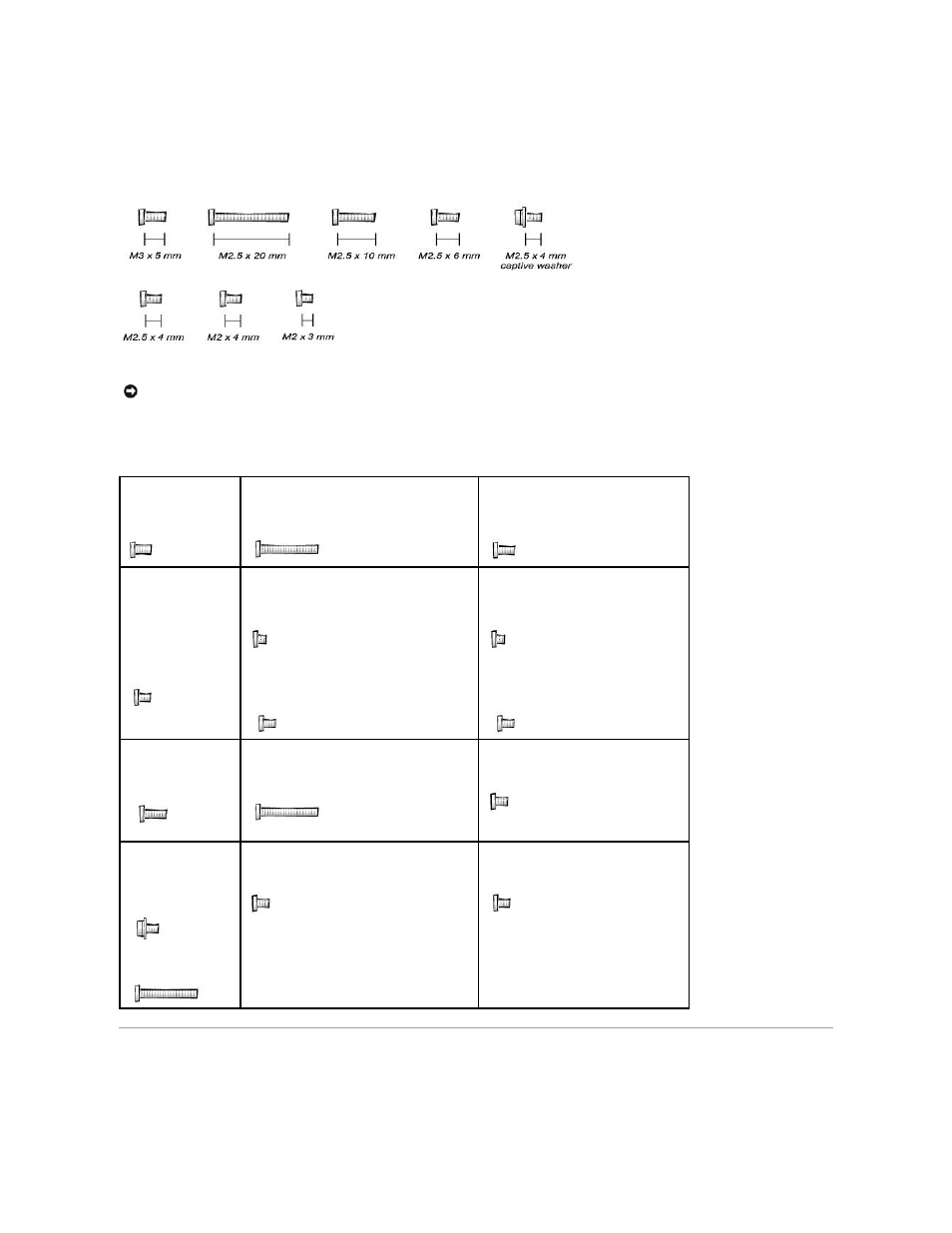
Screw Identification
Before removing and replacing components, photocopy the screw placemat as a tool to help keep track of the screws. The placemat provides the number of
screws and the sizes.
Screw Placemat
System Components
NOTICE:
When reinstalling a screw, you must use a screw of the correct diameter and length. Make sure that the screw is properly aligned with its
corresponding hole, and avoid over tightening.
Hard Drive Door
Security:
M3.0 x 5 mm (1 each)
Keyboard to Bottom Case Assembly:
M2.5 x 20 mm (4 each; one in memory door and
one in Mini PCI card door)
Display to Base:
M2.5 x 6 mm (3 each; 2 at back of system; 1
at flex-cable strain relief)
Display Bezel:
Rubber screw covers (4
each)
Plastic screw covers (2
each)
M2.5 x 4 mm (6 each)
Display Panel to Display Mounting Bracket: 15-
inches
M2.0 x 3 mm (6 each)
Flex-Cable Mounting Bracket to Top Cover:
M2.5 x 4 mm (1 each)
Display Panel to Display Mounting Bracket:
14.1-inches
M2.0 x 3 mm (4 each)
Flex-Cable Mounting Bracket to Top Cover:
M2.5 x 4 mm (1 each)
Video Memory Cache
Card:
M2.5 x 4 mm (2 each)
Palm Rest to
Bottom Case Assembly:
M2.5 x 20 mm (9 each)
LED Board:
M2.0 x 4 mm (2 each)
System Board:
M2.5 x 4 mm captive
washer
(3 each)
M2.5 x 20 mm (1 each)
Fan Assembly:
M2.0 x 4 mm (3 each)
RJ-11/RJ-45 Board Assembly:
M2.5 x 4 mm (1 each)