Usb connectors, Figure b-6 – Dell PowerEdge 2500SC User Manual
Page 8
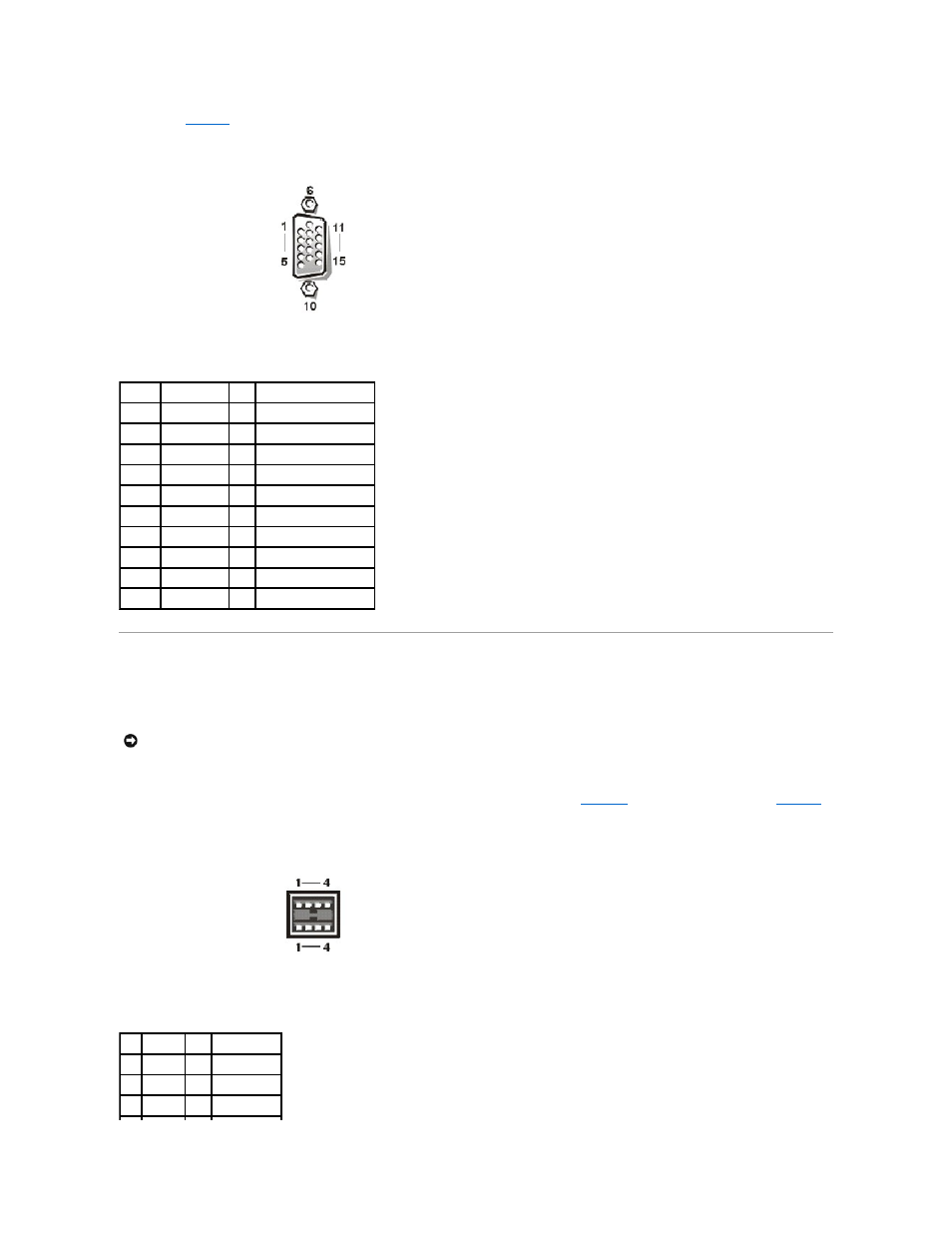
defines the pin assignments and interface signals for the video connector.
Figure B-6. Pin Numbers for the Video Connector
USB Connectors
Your system contains two Universal Serial Bus (USB) connectors for attaching USB-compliant devices. USB devices are typically peripherals such as mice, printers,
keyboards, and system speakers.
illustrates the USB connector and
defines the pin assignments and interface signals for the USB connector.
Figure B-7. Pin Numbers for the USB Connector
Table B-5. Video Connector Pin Assignments
Pin
Signal
I/O Definition
1
RED
O
Red video
2
GREEN
O
Green video
3
BLUE
O
Blue video
4
NC
N/A No connection
5–8, 10 GND
N/A Signal ground
9
VCC
N/A Vcc
11
NC
N/A No connection
12
DDC data out O
Monitor detect data
13
HSYNC
O
Horizontal synchronization
14
VSYNC
O
Vertical synchronization
NOTICE:
Do not attach a USB device or a combination of USB devices that draw a maximum current over 500 milliamperes (mA) per channel or +5 volts
(V). Attaching devices that exceed this threshold may cause the USB ports to shut down. See the documentation that accompanied the USB devices for their
maximum current ratings.
Table B-6. USB Connector Pin
Assignments
Pin Signal
I/O Definition
1
Vcc
N/A Supply voltage
2
DATA
I
Data in
3
+DATA O
Data out